PLANET VC-2400MR48 User Manual
Page 21
User’s Manual of VC-820M / VC-2400MR Series
Blink Indicate that the system is in OS boot procedure or reset to default
FAN1 Alert
Orange
On:
Lights to indicate that the FAN1 failure
FAN2 Alert
Orange
On:
Lights to indicate that the FAN2 failure
FAN3 Alert
Orange
On:
Lights to indicate that the FAN3 failure
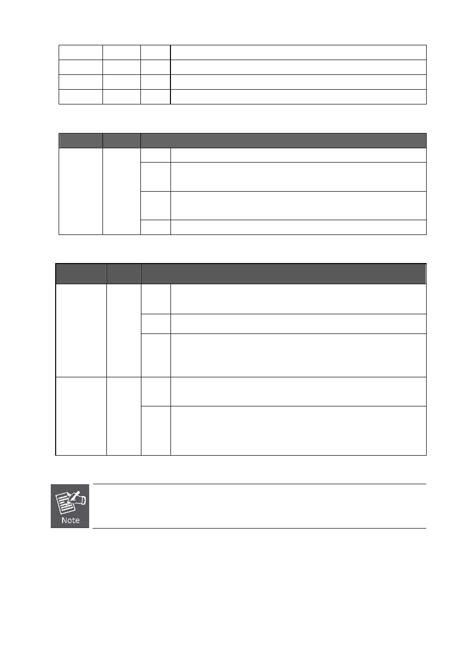
■ Per VDSL Interface ( Port-1 to Port-8)
LED
Color
Function
On:
Indicate that the VDSL link is established
Slow
Blink:
Indicate that the VDSL is at training status with remote CPE
Quick
Blink:
Indicate that the DATA link is actively sending or receiving data over that VDSL
port
VDSL
LNK/Sync
Green
Off:
Indicate that the VDSL is link down
■ 10/100/1000Base-T Copper / 1000Base-SX/LX SFP Interface
(Port-9 and Port-10)
LED
Color
Function
On:
To indicate the link through that port is successfully established with speed
1000Mbps
Blink
: To indicate that the switch is actively sending or receiving data over that port.
1000
LNK/ACT
Green
Off:
If 10/100 LNK/ACT LED is light, it indicates that the port is operating at 10Mbps
or 100Mbps
If LNK/ACT LED is Off, it indicates that the port is link down
On:
To indicate the link through that port is successfully established with speed
10Mbps or 100Mbps
Blink
: To indicate that the switch is actively sending or receiving data over that port.
10/100
LNK/ACT
Green
Off:
If 1000 LNK/ACT LED is light, it indicates that the port is operating at 1000Mbps
If 1000 LNK/ACT LED is Off, it indicates that the port is link down
The 2 Gigabit TP/SFP combo ports are shared with Port 9/10 of VC-820M or Port25/26 of VC-2400MR
Series. Either of them can operate at the same time.
21