3 wiring for vdsl2 ports – PLANET VC-2400MR48 User Manual
Page 29
User’s Manual of VC-820M / VC-2400MR Series
2.3 Wiring for VDSL2 Ports
The VDSL2 port of VC-2400MR series uses one RJ-21 (Telco 50) connector to connect to a patch panel then link up to 24
VDSL CPEs and the VDSL2 port of VC-820M uses eight RJ-11 connectors which can be just directly connected to the
remote CPEs (VC-230, VC-230N, VC-231, VC-234 or other compatible CPE) through structured or unstructured wiring,
such as existing telephone lines. The link between the VDS2L CO Switch port and each CPE can reach speeds of up to
100/100 Mbps under 1000 feet (300 meters) with profile 30a or 18/1 Mbps over distances of up to 5000 feet (1500 meters).
You can hot swap the VDSL2 CPEs without powering down the Managed Switch or disrupting the other switch ports.
Each VC-820M and VC-2400MR series VDSL2 Managed Switch series had built-in Pain Old Telephone service (POTS)
splitter to transmit both VDSL2 traffic and telephone services, such as voice or Fax, through same phone wire. The splitter
routes VDSL2 data (high-frequency) and voice (low-frequency) traffic from the telephone line and Private Branch
exchange (PBX)
switch or Public Switched Telephone Network (PSTN).
The connection diagrams are as the following.
VC-2400MR Series VDSL2 and POTS connection
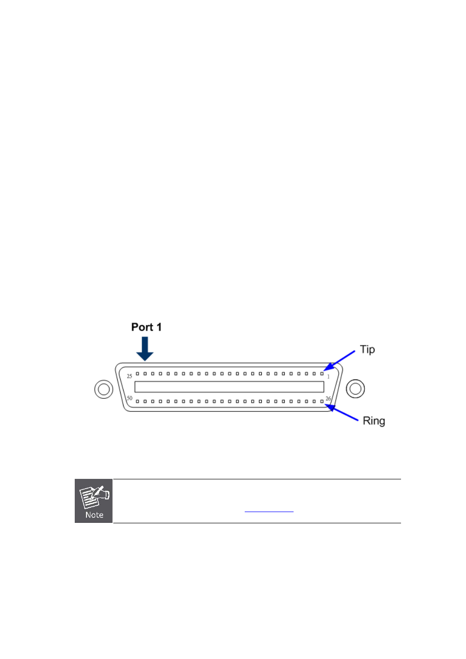
For the 24-Port VDSL or 24-PORT POTS, there are 24 pairs are used for tip and ring. The top row of the Telco RJ-21
connector is tip and the bottom row is ring.
Figure 2-3-1
shows the pin out convention for the RJ-21 connector.
Figure 2-3-1
Pin out convention for the Telco RJ-21 connector of VC-2400MR series
To get the pin assignment of the VDSL/POTS port numbers to the pin numbers on the RJ-21
of the VC-2400MR series, please refer to
for more detail.
The VDSL port and POTS port of VC-2400MR series always connects to a patch panel. The connection between the
VC-2400MR series and the patch panel is made by an RJ-21 Category 5 Telco interface connector and cable, as shown in
Figure 2-3-2
and
Figure 2-3-3
.
29