ProSoft Technology MVI69-DFCM User Manual
Page 66
MVI69-DFCM ♦ CompactLogix or MicroLogix Platform
Reference
DF1 Interface Module
Page 66 of 117
ProSoft Technology, Inc.
November 3, 2008
3 Initialize Module Register space
4 Enable Slave Driver on selected ports
5 Enable Master Driver on selected ports
After this initialization procedure is complete, the module will begin
communicating with other nodes on the network, depending on the configuration.
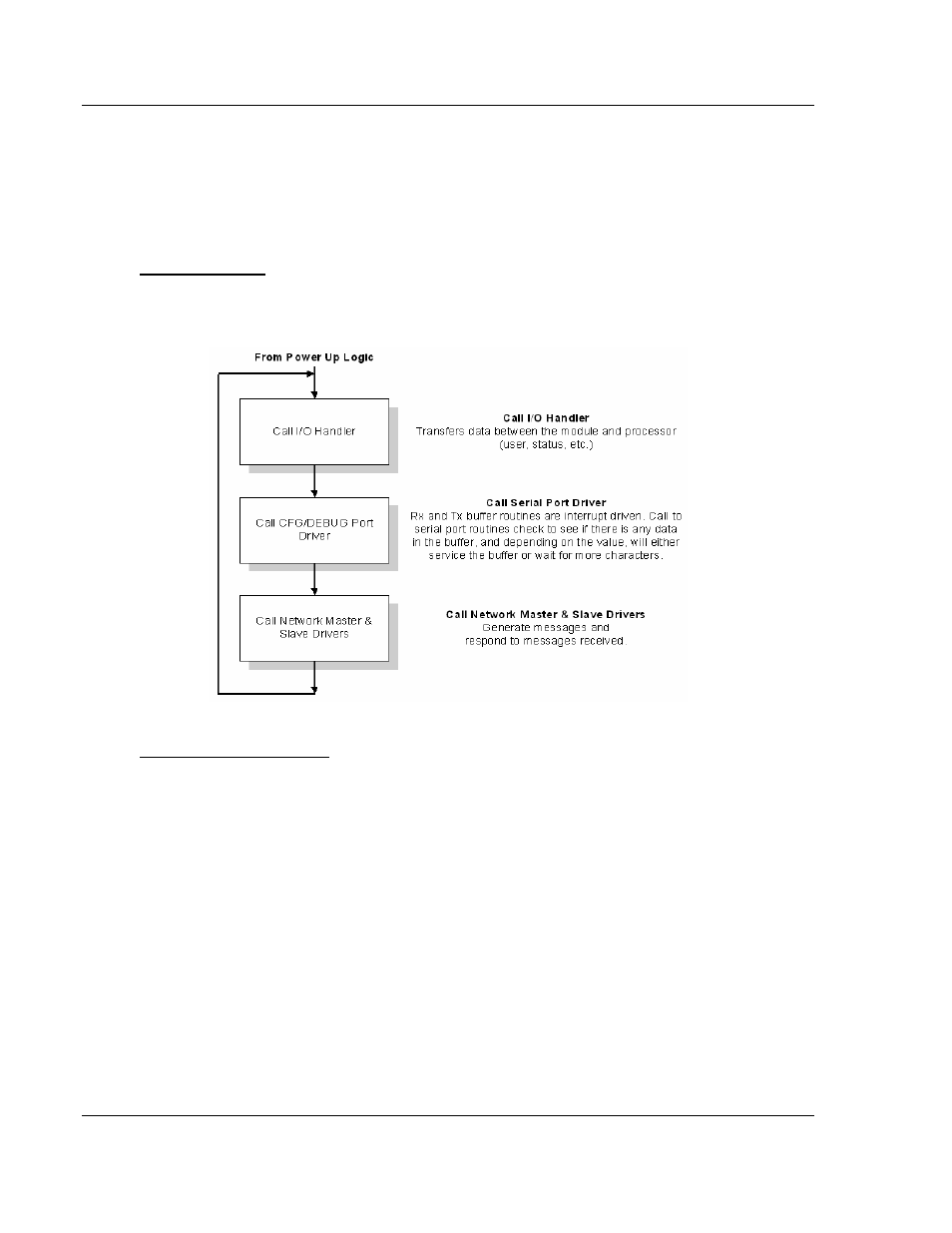
Main Logic Loop
Upon completing the power up configuration process, the module enters an
infinite loop that performs the following functions:
Backplane Data Transfer
The MVI69-DFCM module communicates directly over the CompactLogix or
MicroLogix backplane. Data is paged between the module and the CompactLogix
or MicroLogix processor across the backplane using the module's input and
output images. The update frequency of the images is determined by the
scheduled scan rate defined by the user for the module and the communication
load on the module. Typical updates are in the range of 2 to 10 milliseconds.
The data is paged between the processor and the module using input and output
image blocks. You can configure the size of the blocks using the Block Transfer
Size parameter in the configuration file. You can configure blocks of 60, 120, or
240 words of data depending on the number of words allowed for your own
application.
This bi-directional transference of data is accomplished by the module filling in
data in the module's input image to send to the processor. Data in the input
image is placed in the Controller Tags in the processor by the ladder logic. The
input image for the module may be set to 62, 122, or 242 words depending on
the block transfer size parameter set in the configuration file.