ProSoft Technology MVI69-DFCM User Manual
Page 98
MVI69-DFCM ♦ CompactLogix or MicroLogix Platform
Reference
DF1 Interface Module
Page 98 of 117
ProSoft Technology, Inc.
November 3, 2008
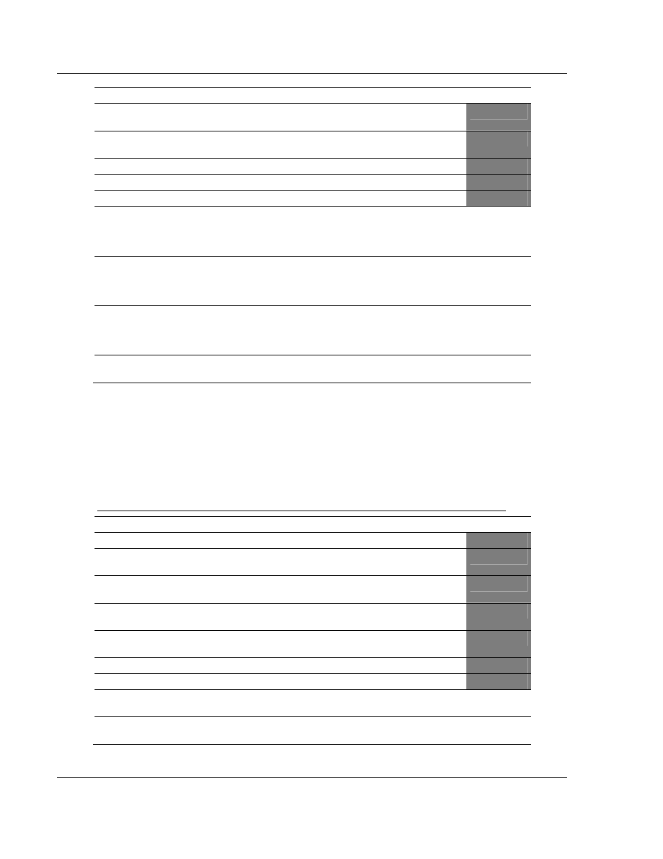
Column
Parameter
Description
Parameter
3
Poll Interval
Minimum number of seconds to wait before polling with
this command.
4
Count
Number of data word values to be considered by the
function.
5
Swap Type Code
Swap type code for command: Always zero (0).
6
Node Address
Address of unit to reach on the data highway.
7
Function Code = 102
Read-Modify-Write Command.
8
File Number
PLC-5 file number to be associated with the command.
If a value of -1 is entered for the parameter, the field will
not be used in the command, and the default file will be
used.
P1
9
Element Number
The parameter defines the element in the file where
write operation will start. If a value of -1 is entered for
the parameter, the field will not be used in the
command, and the default element will be used.
P2
10
Sub-Element Number
This parameter defines the sub-element to be used with
the command. Refer to the AB documentation for a list
of valid sub-element codes. If the value is set to -1, the
default sub-element number will be used.
P3
11
Not Used
This field is not used by the command. Values entered
in this column will be ignored.
P4
This function writes one or more words of data to a PLC data table. This function
should work on the following devices: PLC-5. The command constructed
contains an AND mask and an OR mask. Values in the AND mask have the
following definitions: 0=Reset and 1=Leave the Same. Values in the OR mask
have the following definitions: 0=Leave the Same and 1=Set. The module is
responsible for setting the mask values to correctly construct the message from
the virtual database values.
Function Code #150 - Word Range Write (PLC-5 Command) (ASCII Address)
Column
Parameter
Description
Parameter
1
Enable/Type Word
0=Disabled, 1=Continuous and 2=Conditional.
2
Virtual Database Address
This parameter defines the database address of the first
data point to be associated with the command.
3
Poll Interval
Minimum time in tenths of a second to wait before
polling with this command.
4
Count
Number of data word values to be considered by the
function.
5
Swap Type Code
Swap type code for command: 0=None, 1=Swap words,
2=Swap words & bytes and 3=swap bytes in each word.
6
Node Address
Address of unit to reach on the data highway.
7
Function Code = 150
Word Range Write Command.
8
File String
PLC-5 address as specified as an ASCII string. For
example, N10:300.
P1
9 to 11
Not Used
These fields are not used by the command. Values
entered in these columns will be ignored.
P2 to P4
This function writes one or more words of data to a PLC data table. This function
should work on the following devices: PLC-5.