ProSoft Technology MVI69-DFCM User Manual
Page 78
MVI69-DFCM ♦ CompactLogix or MicroLogix Platform
Reference
DF1 Interface Module
Page 78 of 117
ProSoft Technology, Inc.
November 3, 2008
Cold Boot
This block is sent from the CompactLogix or MicroLogix processor to the module
(output image) when the module is required to perform the cold boot (hardware
reset) operation. This block is sent to the module when a hardware problem is
detected by the ladder logic that requires a hardware reset. The structure of the
control block is shown below:
Offset Description
Length
0 9999
1
1 to n
Spare
247
n=60, 120, or 240 depending on what is entered in the Block Transfer Size parameter (refer to the
configuration file).
5.2.5 Data
Flow
between
MVI69-DFCM Module and CompactLogix or
MicroLogix Processor
The following topics describe the flow of data between the two pieces of
hardware (CompactLogix or MicroLogix processor and MVI69-DFCM module)
and other nodes on the DFCM network under the module's different operating
modes. Each port on the module is configured to emulate a DFCM master device
or a DFCM slave device. The operation of each port is dependent on this
configuration. The sections below discuss the operation of each mode.
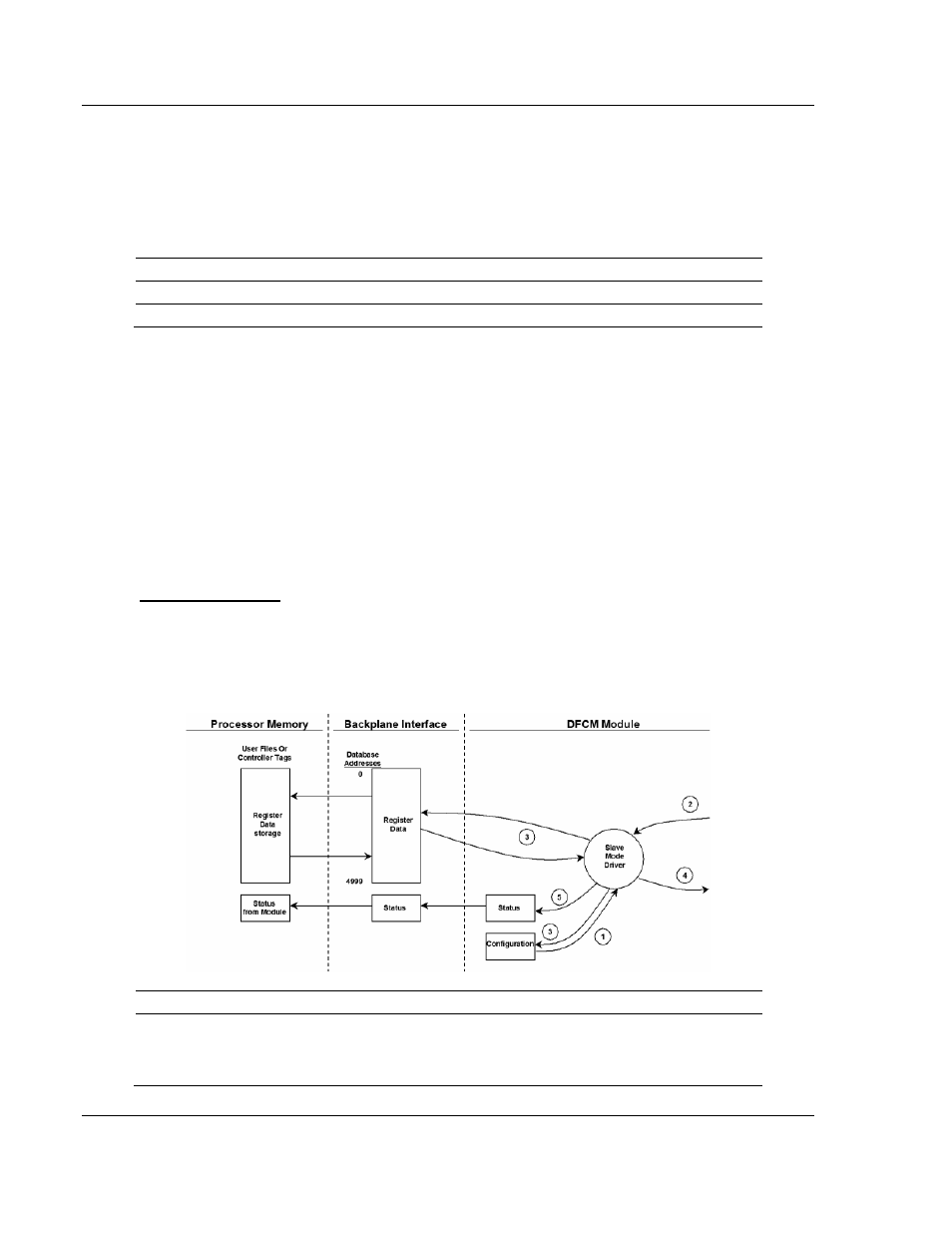
Slave Driver Mode
The Slave Driver Mode allows the MVI69-DFCM module to respond to data read
and write commands issued by a master on the DFCM network. The following
flow chart and associated table describe the flow of data into and out of the
module.
Step Description
1
The DFCM slave port driver receives the configuration information from the internal
Compact Flash disk. This information configures the serial port and define the slave
node characteristics. The module simulates N-files to permit remote access of the
database. Each file has a configurable length of 60, 120, or 240-word registers.