Installing the module in the rack – ProSoft Technology MVI56E-GSC/ GSCXT User Manual
Page 15
MVI56E-GSC ♦ CompactLogix or MicroLogix Platform
Start Here
Enhanced Generic ASCII Serial Communication Module
User Manual
ProSoft Technology, Inc.
Page 15 of 140
May 9, 2014
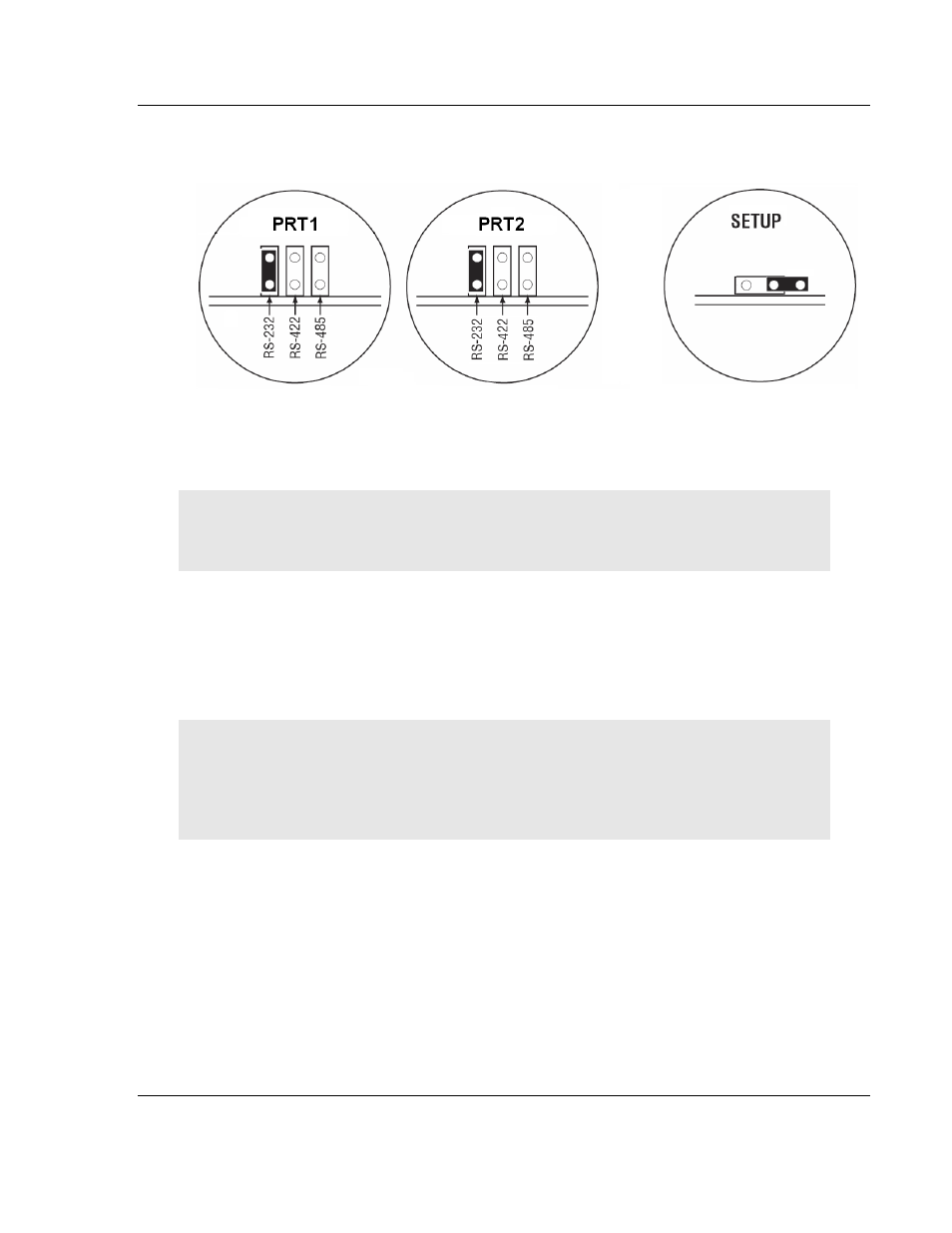
The following illustration shows the MVI56E-GSC jumper configuration, with the
Setup Jumper OFF.
The Setup Jumper acts as "write protection" for the module’s firmware. In "write
protected" mode, the Setup pins are not connected, and the module’s firmware
cannot be overwritten. The module is shipped with the Setup jumper OFF. If you
need to update the firmware, apply the Setup jumper to both pins.
Note: If you are installing the module in a remote rack, you may prefer to leave the Setup pins
jumpered. That way, you can update the module’s firmware without requiring physical access to
the module.
1.7
Installing the Module in the Rack
Make sure your ControlLogix processor and power supply are installed and
configured, before installing the MVI56E-GSC module. Refer to your Rockwell
Automation product documentation for installation instructions.
Warning: You must follow all safety instructions when installing this or any other electronic
devices. Failure to follow safety procedures could result in damage to hardware or data, or even
serious injury or death to personnel. Refer to the documentation for each device you plan to
connect to verify that suitable safety procedures are in place before installing or servicing the
device.
After you have checked the placement of the jumpers, insert the MVI56E-GSC
into the ControlLogix chassis. Use the same technique recommended by
Rockwell Automation to remove and install ControlLogix modules.
You can install or remove ControlLogix system components while chassis power
is applied and the system is operating. However, please note the following
warning.