Synchronization and control, Midi, Time code – Tascam X-48 User Manual
Page 16: Footswitch, Remote (sony 9-pin), Setup
Setup
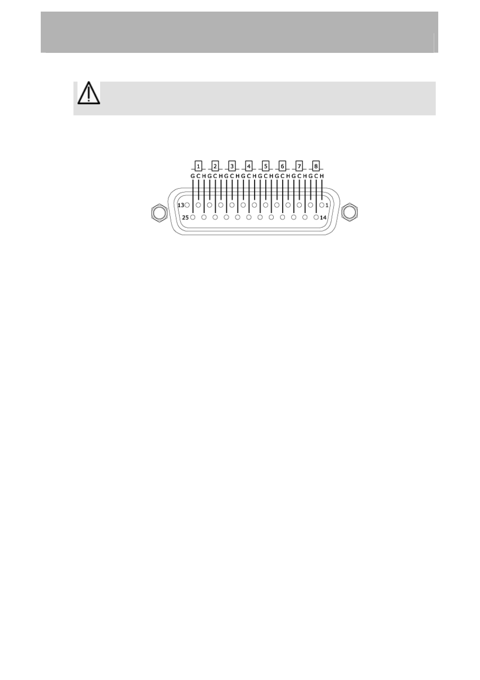
Note: Use only DB25 cables specified by the manufacturer as "Analog" cables.
Many cables look the same on the outside.
The analog DB-25 pinout is pictured below:
Synchronization and Control
This section will deal with the physical connections needed in various synchronized
applications. For details about the appropriate software settings, please refer to Section
'Synchronization'(page 45).
MIDI
There are two MIDI connectors on the rear of the X-48. These are used for MIDI Machine
Control (MMC) and MIDI Time Code (MTC).
IN – This connector receives MTC, which the X-48 can chase, or MMC, which the X-48
can respond to. The front panel MIDI LED will illuminate when valid MIDI signals are
present at this connector.
OUT – This connector outputs MTC any time the transport is in motion. That MTC output
follows the frame rate and output options set for LTC output.
Time Code
There are two ¼” TRS connectors on the rear of the X-48, used for sending & receiving
time code (LTC). These connectors are balanced to allow for long cable runs with minimal
interference. Please refer to page 48-52 for details on time code options.
Footswitch
A normally-open, momentary footswitch may be connected to this ¼” TS connector for
hands free transport and recording operation. NOTE: To operate correctly, as footswitch
must be connected before the X-48 is powered on.
Remote (Sony 9-Pin)
This is also known as “P2” or “Sony P2” or “RS-422”. Various recording consoles and
video controllers support this protocol for transport control and track record enable. This
16