Appendices, Sshqglfhv, 1##,psruwdqw#lqirupdwlrq#uhjduglqj#(0 – Cadac R-Type User Manual
Page 115
Appendices
APP-I
Revision R2005-2
R-Type
$SSHQGLFHV
$1##,PSRUWDQW#LQIRUPDWLRQ#UHJDUGLQJ#(0&#
On the 1st January 1996, new European legislation known as the EMC Directive
came into force. The EMC Directive requires that all electronic equipment manufac-
tured or imported for sale in the EEC must not emit electromagnetic interference that
can impair the performance of other systems or sub-systems. Similarly, the product
must also be immune to a wide range of natural and man-made electromagnetic
interference in its operating environment. Many countries outside the EEC are also
developing or have already put into place similar legislation. In order to conform to
these rules, a number of changes were required to the basic design of our consoles
and modules. One of the main changes is:
All cable ‘screen’ connections are bonded to the frame.
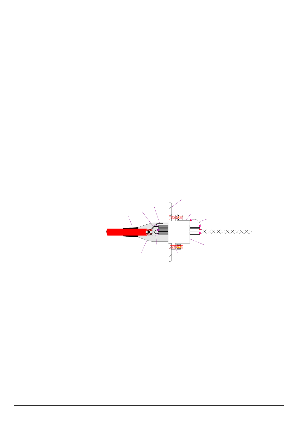
The figure below shows the required connection scheme for XLR connectors.
Please note that in the case of ‘line’ or ‘free’ connectors (XLRs on cables), the 'pig-
tail' formed from the cable screening braid should be as short as practical and sol-
dered to the
shell ground tag. Pin 1 is then connected to the 'pigtail' approximately
halfway between the
shell ground tag and the start point of the cable screening braid.
The twisted pair should be left 'twisted' right up to the signal solder tags.
The chassis half of the connector is bonded to the metalwork with the usual nuts,
bolts and spiky washers. The solder tag should be as long as possible so that the
length of the 'short wire' is a minimum. The twisted pair (from the signal pins - pin 2 &
pin 3) are soldered onto the motherboard adjacent to the 'input RF filter' compo-
nents.
TW ISTED PAIR
W ITH BRAIDED
SCREEN
STRAIN RELIEF
PIGTAIL
SH ELL GROU ND TAG
XLR
M ETAL SHELL
W ITH CO NDUCTIVE FINISH
TW ISTED PAIR
M ETAL PAN EL
SPIKY W ASH ER
LONG SOLDER TAG
SH ORT W IRE
TW ISTED PAIR TO FILTER ON PCB
XLR CHASSIS CON NECTOR W ITH
CONDUCTIVE SURFACE AN D
M ULTI-POINT BOND TO SHELL
OF CABLE CONNECTOR
FIG A-1. XLR connections.