8 remote start of 8019/8020 psu – Cadac R-Type User Manual
Page 26
3-12
R-Type
Revision R2005-2
6161;
5HPRWH#VWDUW#RI#;34<2;353#368
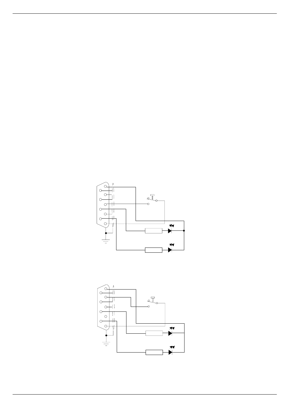
Each 8019/8020 switch-mode power supply provides the following outputs: 13v,
±18v and 48v. Each PSU is fitted with a front panel mounted 9-way 'D-type’ connec-
tor labelled ‘Connections for Remote Start’. If a remote start facility is used, Power
Failure and Over-Temperature LEDs may also be fitted with the remote start
switches if required.
Fig 3-17 and 3-18 shows the circuit for starting up a “system” with a single switch.
This has proved to be the most popular method of connecting the remote start facil-
ity. This circuit can easily be extended to provide a single switch remote for all four
PSUs if required.
NOTE:
■
■
■
■
The remote start switch must be a ‘momentary’ type. You can use 3 separate sin-
gle pole switches for each Power Supply to turn on 13v,±18v and 48v outputs of the
PSU alternatively use one single pole for the whole lot.
■
■
■
■
The remote switch(es) must be mounted on a metal panel.
■
■
■
■
Use shielded cable for the remote switch wiring.
■
■
■
■
The 9-way ‘D-type’ free plug must have a conductive shell. This is to ensure that
the cable shield connects directly to the PSU unit chassis.
Connect the cable shield to the metal panel where the remote start switch(es) are
mounted.
300R
300R
18V
“START” MOMENTARY PUSH BUTTON
VIEW FROM SOLDER
CUP/TAG SIDE
OVER
TEMPERATURE
POWER FAILURE
5
9
4
8
3
2
6
1
7
FIG 3-19. Remote start of 8019 power supply
300R
300R
13V
“START” MOMENTARY PUSH BUTTON
VIEW FROM SOLDER
CUP/TAG SIDE
OVER
TEMPERATURE
POWER FAILURE
5
9
4
8
3
2
6
1
7
FIG 3-20. Remote start of 8020 power supply