3 connecting power supplies, 1 power supply description, Connecting power supplies – Cadac R-Type User Manual
Page 20
3-6
R-Type
Revision R2005-2
616
&RQQHFWLQJ#3RZHU#6XSSOLHV
61614
3RZHU#VXSSO\#GHVFULSWLRQ
The R-Type console is normally supplied with the model 8400 Power Supply Unit.
Each 3U x 19” rack mount power unit supplies all 4 voltages required by the R-Type
console. A single 8400 PSU will power 3 fully loaded R-Type frames.
NOTE: For console configurations with 4 or more frames, the 8019/8020 systems
must be used, see
3.3.7 Switch-Mode Power Supply Units (8019 & 8020)
.
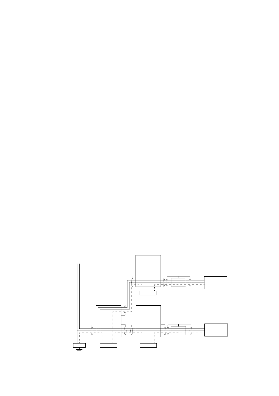
Cadac consoles are designed to allow the use of two independent power supply sys-
tems in a redundant configuration – “main” and “backup”. Both power supply units
are used to power the console system, so that under normal conditions, the ‘load’ is
shared equally between the “main” and “backup” PSU. If a fault occurs in one of the
power units (causing it to ‘shut-down’), the remaining power unit will power the con-
sole (see fig. 3-11).
Designate one power supply unit as “PSU 1" and the other as “PSU 2". PSU 1 and
PSU 2 should be connected to the same
phase and on the same ‘spur’, wherever
possible. In situations where it is necessary to provide a separate ‘feed’ to each PSU
system, make sure that the cable lengths are the same. This is to minimize any
induced a.c. power input noise by ensuring that the “EARTH IMPEDANCE” is the
same for both PSU-systems.
The a.c.-input connectors on each power supply unit have three conductors: ‘LIVE’
(brown), ‘NEUTRAL’ (blue) and ‘EARTH’ (yellow/green). For safety and electromag-
netic compatibility considerations, it is essential that the ‘EARTH’ conductor is con-
nected on all PSUs and the a.c. supply has an ‘EARTH’ conductor that has a
continuous circuit to the “zero-signal reference potential” point in the building. The
ZSRP point in a building is usually found near the place where the a.c. ‘mains’ supply
enters the building (often referred to as the “MAIN GROUND REFERENCE EARTH
ELECTRODE SYSTEM”). The basic concept for correct a.c. mains wiring distribution
is shown in figure 1-1. If you need further information about this complex subject,
please refer to “Grounding Systems and their Implementation” by Charles Atkinson
and Philip Giddins published in the AES Journal Vol. 43, No. 6 – June 1995.
The grounding scheme in CADAC consoles is designed to meet the rigorous EEC
Electromagnetic Compatibility requirements (EMC Directive - 1996). Any RF noise
induced in the console frame(s) is directed to the “local” ZSRP, which is the metal-
work of the power supply units. In order to take full advantage of the “RF noise immu-
nity” capability of the CADAC system, PSU a.c. mains cables and the a.c. mains
supply EARTH conductor must be connected correctly.
GND BAR
GND BAR
AREA
AREA
AREA
GND BAR
PSU1
PSU2
L
N
L
N
N L
BUILDING
FIG 3-11. AC mains grounding diagram (single phase 208-240V)