Figure b-3 load switching diagram – Comtech EF Data SLM-5650A Vipersat User Manual
Page 109
Appendix B - Automatic Switching
B-11
Load Switching
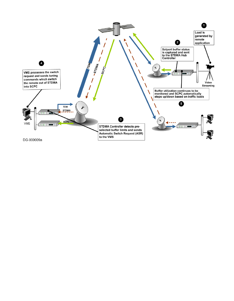
Figure B-3 Load Switching diagram
A load switch is illustrated in figure B-3 using the following process:
1.
A load is generated by an application that is running at a Remote. In this
example, the application is a video stream.
2. The data is connected to the Remote modem/router over an ethernet link for
transmission to the satellite. While the data-stream transmission is in prog-
ress, the Satport buffer status is captured and the Remote’s buffer status is
sent to the STDMA Hub Controller.
3. The STDMA Controller compares the Remote’s pre-selected buffer limits
with its buffer status and, if the buffer status exceeds the preselected limits,
the STDMA Controller increases the time-slot allocated to that channel. If
this brings the buffer status within established limits, no further changes are
made.
4. If the buffer status continues to exceed the preselected limits, the STDMA
Controller sends an ASR to the VMS.
5. The VMS processes the switch request by checking for available resources:
first determining if there is a free demodulator, and then determining the