Signal power level considerations, Signal power level considerations. . . . . . c-15, Figure c-7 signal power levels, remote sitec-15 – Comtech EF Data SLM-5650A Vipersat User Manual
Page 135: E “signal power level considerations” on, Modem
Appendix C - Dynamic Power Control
C-15
Signal Power Level Considerations
Signal Power Level Considerations
There are many parameters to consider when planning and commissioning a site
for satellite transmission. Among the most important are selections for location,
antenna size, and High Power Amplifier. Do not forget entrance link cabling.
These pre-selections determine maximum operability of the site in freedom of
range and limitations. Uplink power gain limitations and cable losses are the
main focus of this section.
The following sub-sections describe the basic segments in adjusting uplink
gains to properly achieve a balance between minimum and maximum transmis-
sion throughputs.
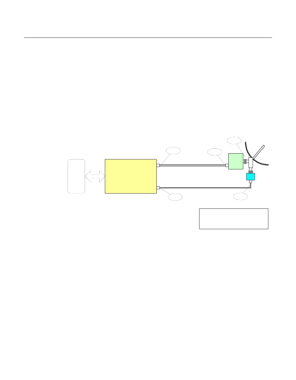
The example block diagram shown in figure C-7 represents a typical remote
station with relevant signal power levels in the transmit and receive chain.
Figure C-7 Signal Power Levels, Remote Site
There is virtually no control over the receive signal levels short of setting the
antenna size, as the demodulator uses a sliding AGC window with an approxi-
mate AGC range of 55 dB at any given data rate.
However, the transmit levels must be carefully controlled. Most BUCs have no
internal gain control and therefore represent a fixed gain block. The output
power is thus directly proportional to the input level, up until the amplifier is
driven to its 1 dB gain compression point (P1dB), beyond which the output
level no longer increases (nonlinear). Some types of amplifiers (such as TWTs)
will actually result in a lower output level as the input is increased. What is
important, therefore, is to know the maximum input level of the BUC, or the
gain and P
out
at the 1 dB compression point. The maximum modulator output
DTE
O
M
T
UC/PA
"BUC"
G=57 dB
LNB
F
F
N
LMR-400 (200 ft)
RG6 (200 ft)
N
Example VSAT Signal Levels
L-Band Version
MAB 8/12/02
Transmit IF
Receive IF
M5 L-Band Modem
-13 dBm
-25 dBm
-65 dBm
-45 dBm
+32 dBm
MODEM
L
A
N