2 inline refractometer sensor, 1 sensor description – K-Patents PR-03 User Manual
Page 11
11
11
11
11
2 Inline refractometer sensor
5
2 Inline refractometer sensor
2.1 Sensor description
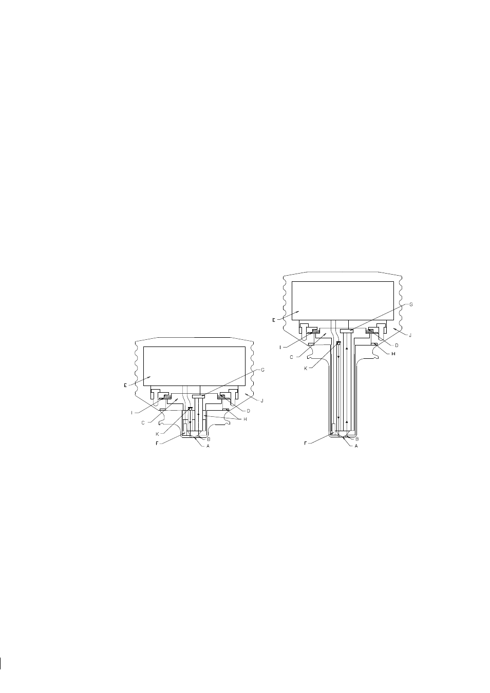
Figure 2.1 below shows cutaway pictures of two refractometer sensors. These sensors are otherwise sim-
ilar in structure, but the sensor on the right has a longer probe. The short probe is the more common
refractometer sensor design, only the Probe Refractometer PR-03-P is built like the sensor to the right in
Figure 2.1.
In the sensor the measurement prism (A) is flush mounted to the surface of the probe tip. The prism is fixed
to the analyzer module (C) which is spring-loaded (D) against the prism gasket (B). The light source is a
light emitting diode (K). The digital image detector (G) is a CCD element consisting of 1024 photocells
in a row integrated on one chip. The image sensor (G) is protected from the process heat by two isolating
parts (H). Excess heat is transferred by a heat conductor (I) to the air cooled sensor cover (J). For automatic
temperature compensation, the sensor tip contains a process temperature probe (F), Pt-100.
Figure 2.1
PR-03 sensor structure
The image detector output is a pulse train as shown in Figure 2.2. The number of high pulses corresponds
to the position of the shadow edge in the optical image and is thus a direct measure of the critical angle.
The image digitizer (E) transforms this pulse train to a serial digital signal. This serial signal transmits to
the Indicating transmitter a package containing temperature data and a complete description of the optical
image.
Note:
K-Patents in-line refractometer PR-03 is using a 1024-pixel CCD-element. To keep the supporting
transmitter software compatible for all K-Patents refractometers, the TEST value (= number of photocells
at the light side) is scaled to the range 8-248. That is, for PR-03 the number of high pulses (Figure 2.2) is
divided by four.