K-Patents PR-03 User Manual
Page 18
18
18
18
18
12
PR-03 instruction manual
3.2.2.1 Connecting with sensor
The sensor end of the interconnecting cable is terminated by a plug. The plug goes into the cable plug
socket on the sensor head. After connecting the cable with the sensor, join the two connector protecting
caps to keep them clean inside.
The Indicating transmitter end of the interconnecting cable has leads numbered from 1 to 7 to be connected
to the terminals with the same numbers on the Power supply card. The seven leads to the plug on the cable
are colored Red, Blue, Black, Red, Blue, Black and Black.
3.2.2.2 AC power connection
The primary AC power is connected to a separate terminal strip 39/40/41 marked POWER in the lower
right-hand corner of the Power supply card (Figure 3.5). The three terminals are marked 39/L, 40/N and
41/ground symbol. The connection is made by inserting each lead into the corresponding slot and tightening
the screws above the slots (Figure 3.7).
The power terminals Line and Neutral are directly connected to the transformer primary loop, and galvani-
cally separated from the rest of the instrument. The ground terminal (41) is connected to the bottom plate of
the Indicating transmitter, to the transformer shield winding and to the outer shield of the interconnecting
cable.
NEUTRAL
LINE
GROUND
Figure 3.7
Power terminals on the Power supply card
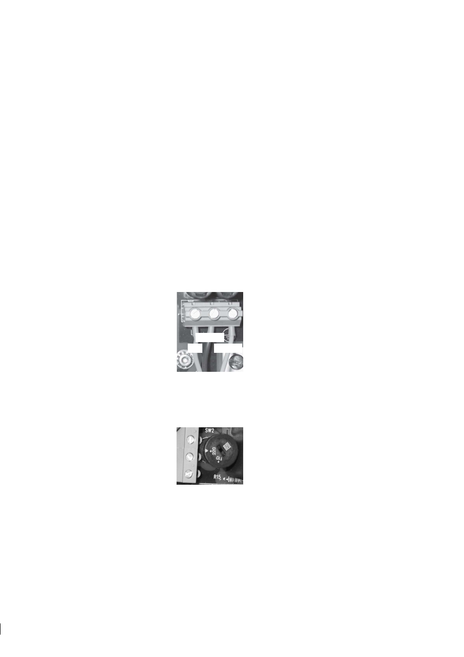
Important:
Before connecting the IT-R power, check the position of the power selector switch, marked
SW2 on the Power supply card. The power selector switch has two positions: 220–240 V/50–60 Hz or
100–115 V/50–60 Hz.
Figure 3.8
Power selector switch in the 220 V position
3.2.2.3 +24 V DC power connection
The primary DC power is connected to a separate terminal strip 39/40/41 marked POWER in the lower right-
hand corner of the Power supply card (Figure 3.5). The terminals are marked 39/+24V, 40/0 and 41/ground