K-Patents PR-03 User Manual
Page 56
56
56
56
56
50
PR-03 instruction manual
(a)
(b)
Figure 6.3
The prism plate, the prism and prism gaskets
9. Now the Analyzer module PR-9001 is assembled. It should be checked before mounting into the sensor
head:
1. Clean the window of the CCD-element (V), Figure 6.2. Attach the Image detector card to the
Analyzer module by the two screws (F) with conical heads. Connect electrically all cards, with
connectors (A), (B), (C), and (D).
2. Connect the Indicating transmitter, and inspect the optical image at the Raw data display (key se-
quence Calibrate / Optical image).
3. The optical image must form a smooth curve. Dips or separate single points indicate that the optical
surfaces (e.g. the CCD window) are not clean.
Important:
The prism must be covered to exclude external light.
4. When the image is OK, switch power off and disconnect all cards. Dismount the Image detector
card from the analyzer module.
10. Now the Analyzer module is ready for sensor assembly.
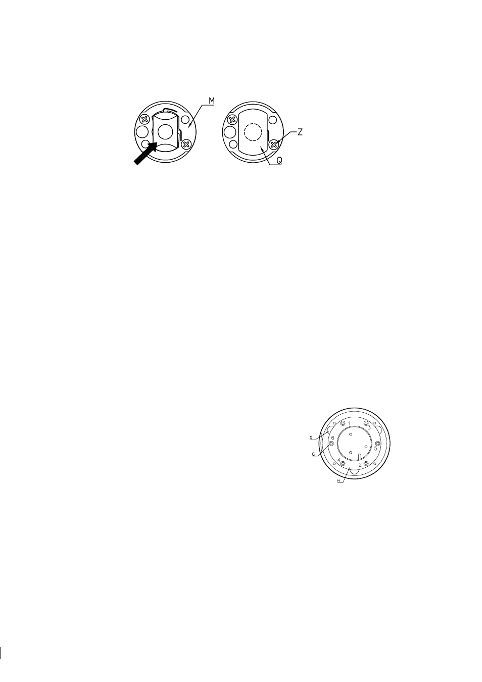
6.3.3 Assembling the sensor
1. Fit the Analyzer module into the sensor head. Note the alignment pin (R),
Figure 6.1.
2. Mount the thermal conductor (K) with the holes aligned to the screw holes.
Mount the disk spring (J). Note the position of the disk spring on the detail
(J), Figure 6.1.
3. Mount the disk spring holder (H). Faster the six screws (G) in small steps
following the pattern of numbers in Figure 6.4. Continue until the holder
surface is flush with the surfaces of the three notches (S). No step should be
felt with the finger tip.
Figure 6.4
Tightening the
spring holder screws
4. Mount the Image detector card with the screws (F), Figure 6.1. First tighten the two guiding screws with
conical heads, then the third screw. Lock the screws with e.g. nail polish.
5. Mount the Image digitizer card with the screws (E). Connect (B), (C) and (D).