2 mounting indicating transmitter – K-Patents PR-03 User Manual
Page 16
16
16
16
16
10
PR-03 instruction manual
Furthermore, the Indicating transmitter accepts four input switches which can be configured for example to
signal HOLD during external wash or to contain different scale settings each (see Section 5.6, “Configuring
input switches”).
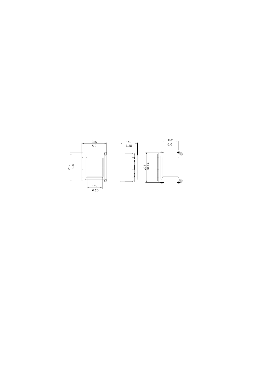
3.2 Mounting Indicating transmitter
The Indicating transmitter should preferably be located in an easily accessible, well lighted and dry area.
The enclosure must not be exposed to rain or direct sunlight. Avoid vibration. Take interconnecting cable
length into consideration when choosing mounting location.
The enclosure is mounted vertically on an upright surface (wall) using four mounting feet, see Figure 3.4.
Important:
Do not drill mounting holes in the enclosure as that will affect the protection class of the
enclosure and may expose the electronics of the IT-R.
Figure 3.4
Mounting the Indicating transmitter
Note:
The LCD display has an operating temperature range of 0–50
◦
C and a storage temperature range of
-20–60
◦
C. If exposed to very low storage temperatures, let the IT-R reach the ambient temperature before
turning it on, as the LCD may not be able to display anything in temperatures below zero.
3.2.1 Mounting the Interconnecting cable
The interconnecting cable PR-8300 is made at the K-Patents factory according to the specifications given
in your order (see Section 9.4). The maximum length of an interconnecting cable is 100 meters (330 feet).
When mounting the cable, check that the ends easily reach the sensor respectively the IT-R.
Warning!
Do not try to shorten or lengthen the interconnecting cable! If a new cable is needed for example
!
after the IT-R has been moved further away from the process line, you can order a spare part cable from
K-Patents or your local K-Patents representative.