K-Patents PR-03 User Manual
Page 26
26
26
26
26
20
PR-03 instruction manual
4.1.3.2 Mounting and connecting Relay unit -WR
The Relay unit -WR is always mounted directly underneath the IT-R. If the IT-R and the Relay unit -WR are
delivered together, they are already fully connected. If the Relay unit is delivered separately, the connection
cable is included in the Relay unit delivery. The cable is plugged in the P2 plug on the IT-R’s processor
card (next to the sensor cable, see Figure 3.5). The relay contacts go to the connector strip.
4.1.4 Mounting and connecting prism wash systems
The prism wash system for steam is described by Figures 4.7 and 4.8 and for high pressure water by Fig-
ure 4.9.
4.1.4.1 Recommended wash pressures and times
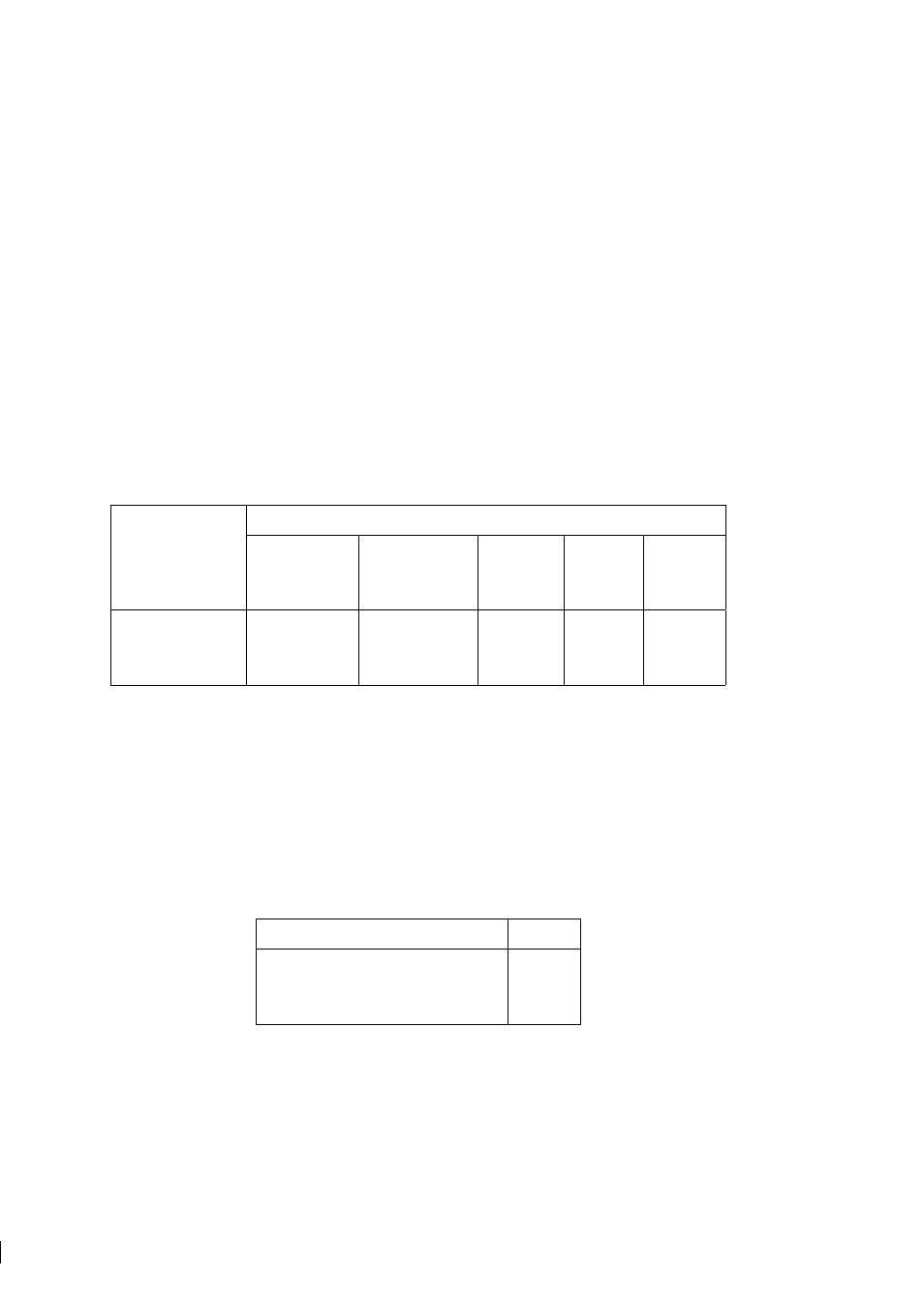
The recommended wash pressures and times are given in Table 4.1 below.
Wash medium pressure
Minimum
Maximum
Wash time
Recovery
Interval
above process
allowed
pressure
pressure
Steam
2 bar (30 psi)
6 bar (90 psi)
3–5 s
20–30 s
20–30 min
Water
2 bar (30 psi)
6 bar (90 psi)
10–15 s
20–30 s
10–20 min
High pressure water
40 bar (600 psi)
70 bar (1000 psi)
10–15 s
20–30 s
10–20 min
Table 4.1
Recommended prism wash parameters
Important:
In steam wash, do not exceed the recommended wash times, because some process media may
burn to the prism surface if steamed for longer time. In case of coating, shorten the wash interval.
Note:
In water wash, water temperature should be above the process temperature.
Note:
The check valve pressure drop is 0.7 bar (10 psi).
4.1.4.2 Prism wash nozzles
Select wash nozzle according to wash medium and refractometer model, Table 4.2.
PR-03-A
Pressurized water sanitary nozzle -WP
PR-3366
Steam sanitary nozzle -SN
PR-3365
Water nozzle -WN
PR-3364
Table 4.2
Prism wash nozzle selection