K-Patents PR-03 User Manual
Page 55
55
55
55
55
6 Regular maintenance
49
5. Disconnect the ribbon cable (B), the LED lead (C), and the temperature element lead (D).
6. Remove the Image digitizer card kept by four M4 screws (E).
7. Remove the Image detector card kept by three M3 screws (F).
Note:
Removing the screws may introduce a slight calibration error.
8. Loosen carefully the six M4 screws (G) of the disc spring holder. Turn in small steps, alternating
between the screws.
Warning!
Never touch the screws (G) when the instrument is in the process line!
!
9. Remove the disc spring holder (H), the disc spring (J), and the thermal conductor (K).
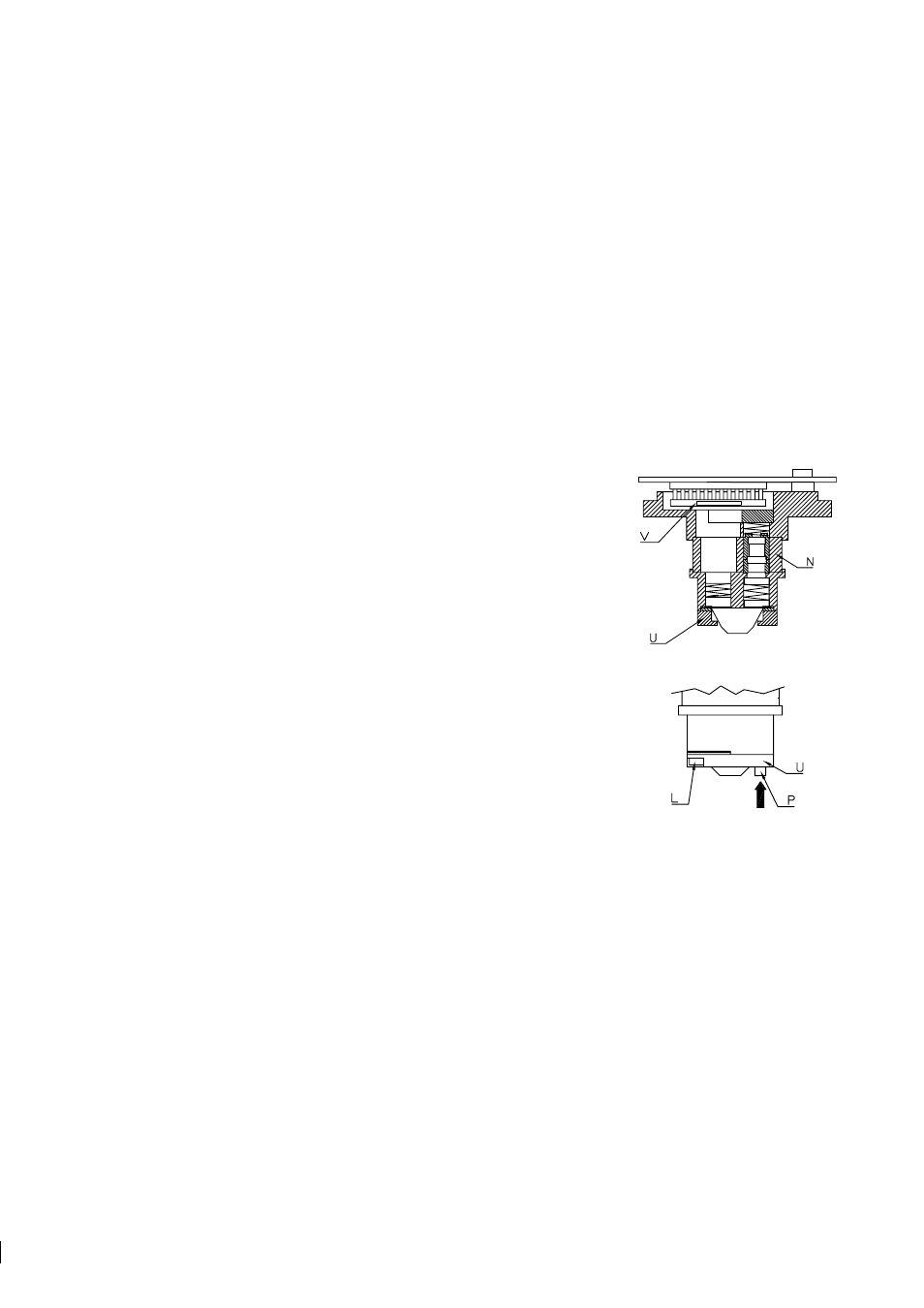
6.3.2 Replacing the prism and prism gaskets
1. Lift out the Analyzer module, Figure 6.2. The module does not turn
due to the alignment pin (R).
Note:
The thermal insulator (N) is per-
manently glued at both ends.
Note:
The Heavy-duty process refractometer PR-03-M74 with a sap-
phire prism has a special Analyzer module PR-9101 and a prism sup-
port due to the 1 mm higher sapphire prism.
2. To remove the prism, push it gently against the springs in the prism
plate (M), as indicated by an arrow in Figure 6.2 (b).
3. Clean the prism.
Important:
Do not leave any finger prints on any of
the four optical surfaces!
4. Put the prism in place pushing gently against the springs of the prism
plate (M). The direction of the force is indicated by an arrow in Fig-
ure 6.3 (a). To make sure the prism is in correct position, press the
prism in the opposite direction of the arrow.
5. Put the prism in place pushing gently against the springs of the prism
plate (M). The direction of the force is indicated by an arrow in Fig-
ure 6.3 (a). To make sure the prism is in correct position, press the
prism in the opposite direction of the arrow.
6. Cover the prism by a new prism gasket (with the center hole uncut)
according to Figure 6.3 (b).
(a)
(b)
Figure 6.2
The
Analyzer module
7. Put the prism support (U) upon the gasket. Keep the gasket in place with a fingertip in the middle.
Check that the gasket is symmetrical around the middle of the prism surface. Tighten the screws (L) to
the bottom, Figure 6.2 (b).
8. Check that the temperature sensor (P) is properly springloaded. In outer position, the sensor tip is level
with the prism surface Figure 6.2 (b). It should flex inwards 2-3 mm as indicated by an arrow, but return
to the outer position.