MovinCool Office Pro 63 Service Manual User Manual
Page 50
Repair Section
50
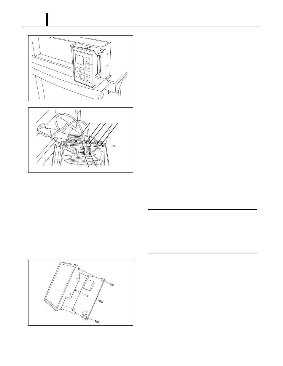
3) Slowly slide control panel assembly out of box.
4) Disconnect the following connectors from the
control board:
(A) J201 (10-pin) Wire Harness, Relay Board to
Control
(B) J101 (2-pin) Room Temperature Thermistor
(C) J102 (2-pin with black tape) Freeze
Protection Thermistor
(D) J103 (2-pin) Drain Tank Switch
(E) J104 (2-pin) High Pressure Switch
(F) J106 (2-pin) Output signal terminal
(G) J108 (2-pin) Input signal terminal
< NOTE >
Mark each of the 2-pin connectors with a
different color marker to ensure the correct
orientation when they are reconnected or label
all wire sets with tape. Numbering the wire sets
from (A) through (G).
5) Remove the five (5) screws from the control
board on the control panel assembly. Remove
the control board.
I002181
I002182
A
B C
E
F
G
D
I001804