ONICON F-2600 User Manual
Page 20
11451 Belcher Road South, Largo, FL 33773 • USA • Tel +1 (727) 447-6140 • Fax (727) 442-5699 • [email protected]
F-2600 & F-2700 Vortex Flow Meter Manual 02/15 - 0808-7 / 19204
Page 20
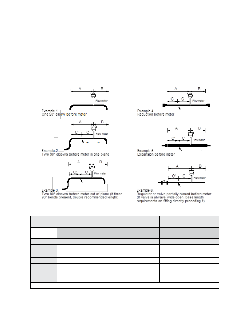
2.1.2 Unobstructed Flow Requirements
Select an installation site that will minimize possible distortion in the flow profile. Valves,
elbows, control valves and other piping components may cause flow disturbances. Check
your specific piping condition against the examples shown below. In order to achieve
accurate and repeatable performance, install the flow meter using the recommended
number of straight run pipe diameters upstream and downstream of the sensor.
Note: For liquid applications in vertical pipes, avoid installing with flow in the downward
direction because the pipe may not be full at all points. Choose to install the meter with
flow in the upward direction, if possible.
Minimum Required
Upstream Diameters
Minimum Required
Downstream Diameters
No Flow
Straightener
With Flow Straightener
No Flow
Straightener
With Flow
Straightener
Example
A
A
C
C’
B
B
1
10 D
N/A
N/A
N/A
5 D
5 D
2
15 D
10 D
8 D
2 D
5 D
5 D
3
30 D
15 D
13 D
2 D
5 D
5 D
4
10 D
N/A
N/A
N/A
5 D
5 D
5
20 D
10 D
8 D
2 D
5 D
5 D
6
50 D
25 D
23 D
2 D
5 D
5 D
D = Internal diameter of channel.
Figure 4. Recommended Pipe Length Requirements for Installation
Flow straightener
(if used)
Flow straightener
(if used)
Flow straightener
(if used)
Flow straightener (if used)
Flow straightener
(if used)