ONICON F-2600 User Manual
Page 43
11451 Belcher Road South, Largo, FL 33773 • USA • Tel +1 (727) 447-6140 • Fax (727) 442-5699 • [email protected]
F-2600 & F-2700 Vortex Flow Meter Manual 02/15 - 0808-7 / 19204
Page 43
2.7.2 4-20
mA OUTPUT CONNECTIONS
The externally powered versions of the meters have a single 4-20 mA loop powered
output. Two additional loops are available on the optional communication board. The 4-20
mA loop current is controlled by the meter electronics. The electronics must be wired in
series with the sense resistor or current meter. The current control electronics require a
minimum of 12 volts at the input terminals to operate correctly.
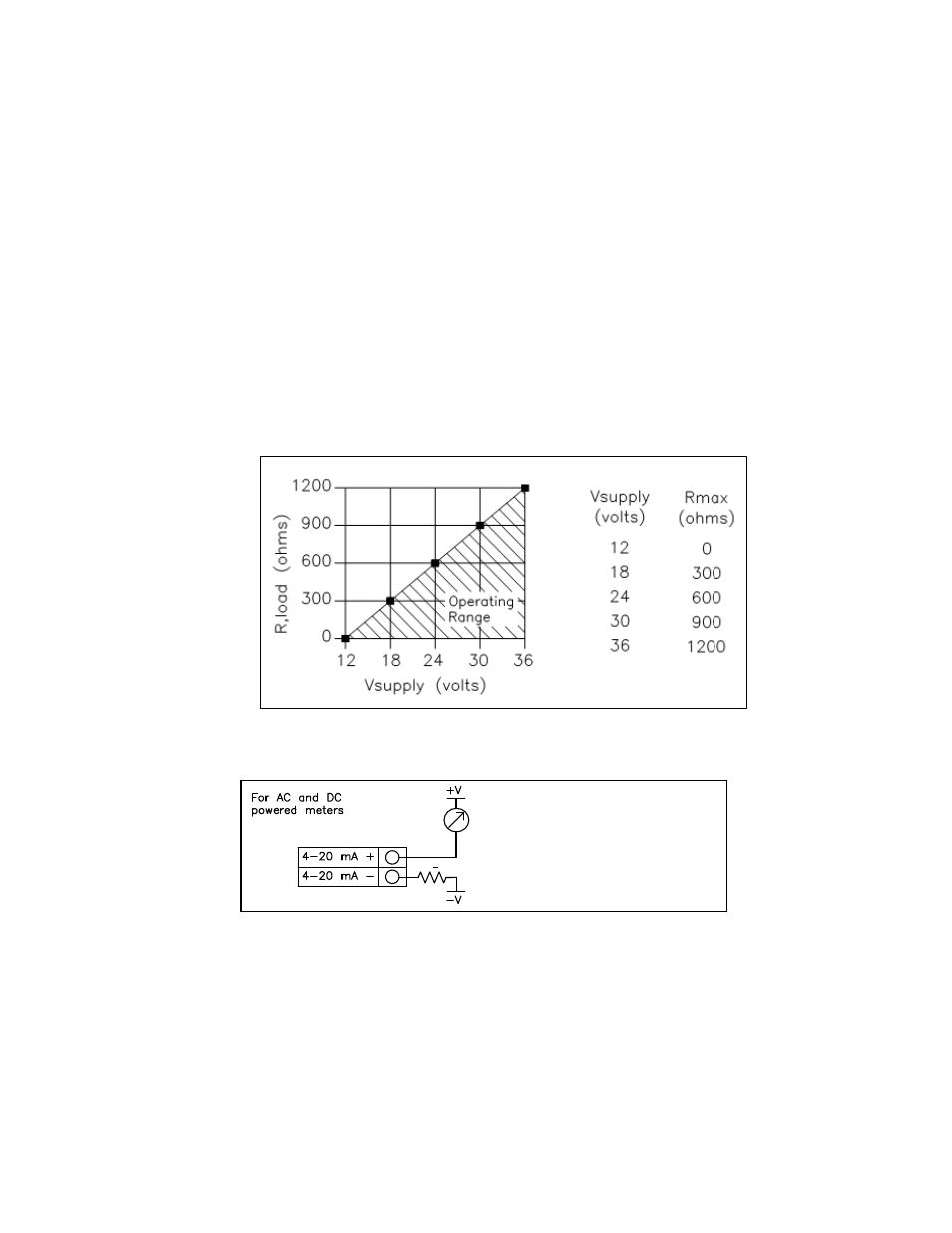
The maximum loop resistance (load) for the current loop output is dependent upon the
supply voltage and is given in Figure 30. The 4-20 mA loop is optically isolated from the
flow meter electronics.
R
load
is the total resistance in the loop, including the wiring resistance (R
load
= R
wire
+ R
sense
).
To calculate R
max
, the maximum R
load
for the loop, subtract the minimum terminal voltage
from the supply voltage and divide by the maximum loop current, 20 mA. Thus:
The maximum resistance R
load
= R
max
= (V
supply
– 12V) / 0.020 A
Figure 30. Load Resistance Versus Input Voltage
R
L
> 250
4-20 mA voltage = +V
For Hart communications,
signal loop must have a
minimum of 250 ohms load
resistance R
L
.
mA
Meter
Figure 31. Isolated 4–20 mA Output Using External Power Supply