ONICON F-2600 User Manual
Page 22
11451 Belcher Road South, Largo, FL 33773 • USA • Tel +1 (727) 447-6140 • Fax (727) 442-5699 • [email protected]
F-2600 & F-2700 Vortex Flow Meter Manual 02/15 - 0808-7 / 19204
Page 22
2.2.1 Wafer-Style Flow Meter Installation
Install the wafer-style meter between two conventional pipe flanges of the same nominal
size as the flow meter. If the process fluid is a liquid, make sure the meter is located where
the pipe is always full. This may require locating the meter at a low point in the piping
system. Note: Vortex flow meters are not suitable for two-phase flows (i.e., liquid and gas
mixtures). For horizontal pipelines having a process temperature above 300° F, mount the
meter at a 45o or 90o angle to avoid overheating the electronics enclosure. To adjust the
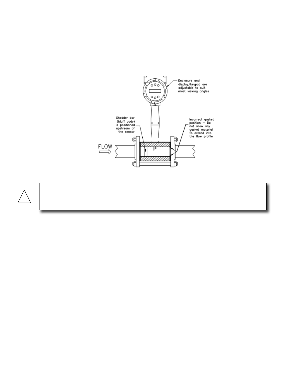
viewing angle of the enclosure or display/keypad, see page 34 and 35.
Figure 6. Wafer-Style Flow Meter Installation
When installing the meter make sure the section marked with a flow arrow is positioned
upstream of the outlet, with the arrow head pointing in the direction of flow. (The mark
is on the wafer adjacent to the enclosure mounting neck.) This ensures that the sensor
head is positioned downstream of the vortex shedder bar and is correctly aligned to the
flow. Installing the meter opposite this direction will result in completely inaccurate flow
measurement. To install the meter:
1. Confirm that the installation site meets the required minimum upstream and
downstream pipe diameters. Turn off the flow of process gas, liquid or steam. Verify
that the line is not pressurized.
2. Insert the studs for the bottom side of the meter body between the pipe flanges. Place
the wafer-style meter body between the flanges with the end stamped with a flow arrow
on the upstream side, with the arrow head pointing in the direction of flow. Center the
meter body inside the diameter with respect to the inside diameter of the adjoining
piping.
3. Position the gasket material between the mating surfaces. Make sure both gaskets are
smooth and even with no gasket material extending into the flow profile. Obstructions
in the pipeline will disturb the flow and cause inaccurate measurements.
4. Place the remaining studs between the pipe flanges. Tighten the nuts in the sequence
shown in Figure 5. Check for leaks after tightening the flange bolts.
!
CAUTION
When using toxic or corrosive gases, purge the line with inert gas for a minimum of four hours at
full gas flow before installing the flow meter.