ONICON F-2600 User Manual
Page 21
11451 Belcher Road South, Largo, FL 33773 • USA • Tel +1 (727) 447-6140 • Fax (727) 442-5699 • [email protected]
F-2600 & F-2700 Vortex Flow Meter Manual 02/15 - 0808-7 / 19204
Page 21
2.2 F-2600 SERIES IN-LINE FLOW METER INSTALLATION
Install the in-line flow meter between two conventional pipe flanges as shown in Figures 6 and
7. Table 1 provides the recommended minimum stud bolt lengths for wafer-style meter body size
and different flange ratings.
The meter's inside diameter is equal to the same size nominal pipe ID in schedule 80. For
example, a 2” meter has an ID of 1.939” (2” schedule 80). Do not install the meter in a pipe with
an inside diameter smaller than the inside diameter of the meter. For schedule 160 and higher
pipe, a special meter is required. Consult the factory before purchasing the meter.
In-line meters require customer-supplied gaskets. When selecting gasket material, make sure that
it is compatible with the process fluid and pressure ratings of the specific installation. Verify that
the inside diameter of the gasket is larger than the inside diameter of the flow meter and adjacent
piping. If the gasket material extends into the flow stream, it will disturb the flow and cause
inaccurate measurements.
Flange Bolt Specifications
Stud Bolt Lengths for Each Flange Rating (inches)
Line Size
Class 150
and PN16
Class 300
and PN40
Class 600
and PN64
1 "
6.00
7.00
7.50
1½ "
6.25
8.50
9.00
2 "
8.50
8.75
9.50
3 "
9.00
10.00
10.50
4 "
9.50
10.75
12.25
Table 1. Minimum Recommended Stud Bolt Lengths for Wafer Meters
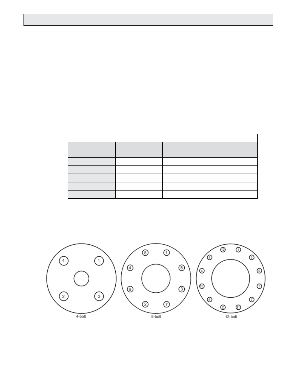
The required bolt load for sealing the gasket joint is affected by several application-dependent
factors; therefore, the required torque for each application may be different. Refer to the ASME
Pressure Vessel Code guidelines for bolt tightening standards.
Figure 5. Flange Bolt Tightening Sequence