ONICON F-2600 User Manual
Page 86
11451 Belcher Road South, Largo, FL 33773 • USA • Tel +1 (727) 447-6140 • Fax (727) 442-5699 • [email protected]
F-2600 & F-2700 Vortex Flow Meter Manual 02/15 - 0808-7 / 19204
Page 86
The floating point registers with values in display units are scaled to the same units as
are displayed, but are instantaneous values that are not smoothed. If display smoothing
is enabled (non-zero value entered in the Display TC item in the Display Menu), then the
register values will not agree exactly with the displayed values.
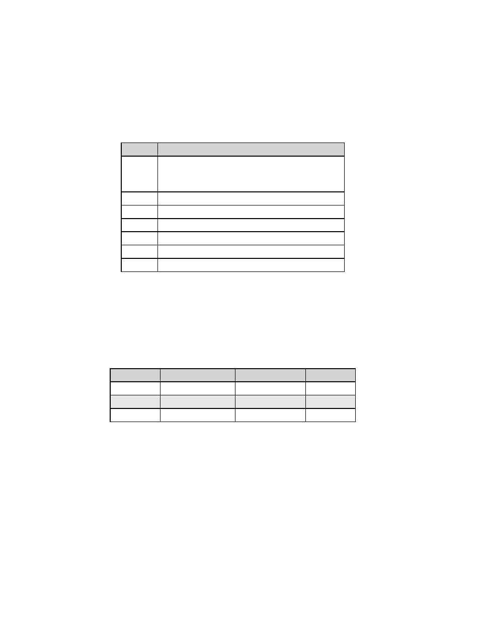
Exception Status Definitions
The Read Exception Status command (function code 07) returns the exception status byte,
which is defined as follows. This byte may be cleared by setting “coil” register #00003
(function code 5, address 2, data = 0xff00).
Bit(s)
Definition
0-1
Byte order (see Modbus Order on page 2)
0 = 3-2:1-0 1 = 2-3:0-1
2 = 1-0:3-2 3 = 0-1:2-3
2
Temperature sensor fault
3
Pressure sensor fault
4
A/D converter fault
5
Period overflow
6
Pulse overflow
7
Configuration changed
Discrete Input Definitions
The status of the three alarms may be monitored via the Modbus Read Discrete Input
command (function code 02). The value returned indicates the state of the alarm, and will
be #1 only if the alarm is enabled and active. A zero value is transmitted for alarms that
are either disabled or inactive.
Registers
Variable
Function Code Address
10001
Alarm #1 state
02
0
10002
Alarm #2 state
02
1
10003
Alarm #3 state
02
2