Warning – ONICON F-2600 User Manual
Page 81
11451 Belcher Road South, Largo, FL 33773 • USA • Tel +1 (727) 447-6140 • Fax (727) 442-5699 • [email protected]
F-2600 & F-2700 Vortex Flow Meter Manual 02/15 - 0808-7 / 19204
Page 81
4.2 MODBUS COMMUNICATIONS
Applicable Flow Meter Models: ONICON F-2600 & F-2700 Series Mass Flow Meters with Modbus
communication protocol and firmware version 4.00.58 and above.
Overview
This document describes the preliminary implementation of the Modbus communication protocol
for use in monitoring common process variables in the ONICON F2600 Series Mass Vortex Flow
Meter. The physical layer utilizes the half-duplex RS-485 port and the Modbus protocol.
Reference Documents
The following documents are available online from www.modbus.org.
Modbus Application Protocol Specification V1.1
Modbus Over Serial Line Specification & Implementation Guide V1.0
Modicon Modbus Protocol Reference Guide PI–MBUS–300 Rev. J
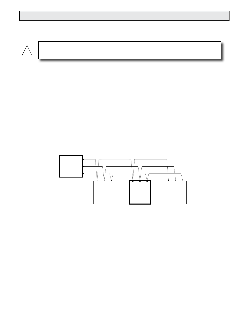
4.2.1 Wiring
An RS-485 daisy chained network configuration as depicted below is recommended. Do
not use a star, ring, or cluster arrangement.
RS-485 -
RS-485 +
RS-485 GND
RS-485 Master
Vortex Meter
RS
-485
-
RS
-485
+
RS
-485
GND
RS
-485
-
RS
-485
+
RS
-485
GND
Other Device 2, etc.
RS
-485
-
RS
-485
+
RS
-485
GND
Other Device 1
Figure 53. RS-485 Wiring (MODBUS)
PIN LABELING (AMONG DEVICES)
“RS-485 –” = “A” = “TxD-/RxD-” = “Inverting pin”
“RS-485 +” = “B” = “TxD+/RxD+” = “Non-Inverting pin”
“RS-485 GND” = “GND” = “G” = “SC” = “Reference”
!
WARNING
Place controls in manual mode when making configuration changes to the vortex meter.