Online power – OnLine Power Protector 3 User Manual
Page 15
OnLine Power
2-5
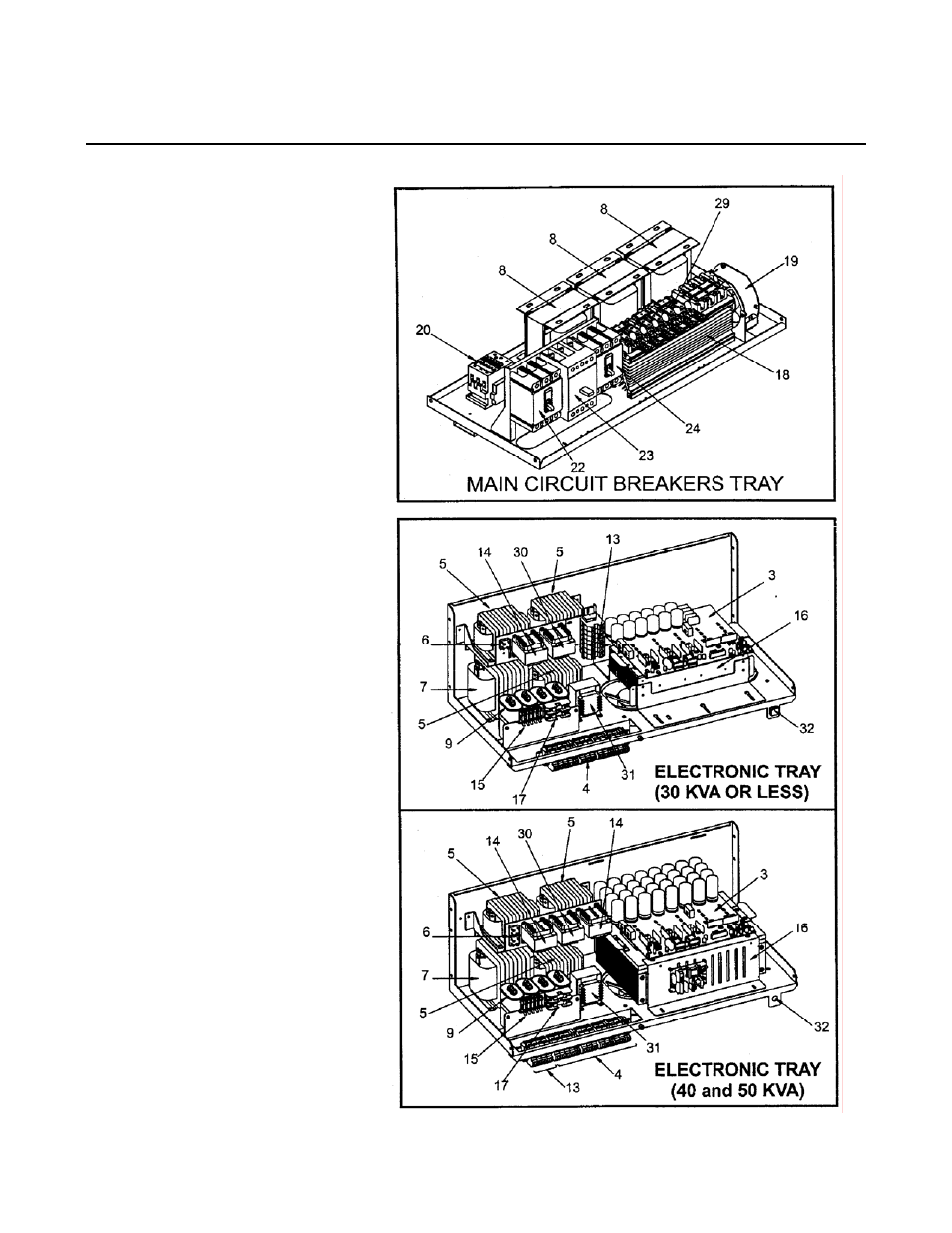
ILLUSTRATION 2-3: SUB-ASSEMBLY COMPONENT LOCATION
1. Output Transformer (T1)
2. Auto-Transformer (T3)
3. Power Board Assembly (A1)
4. Input/Output/Battery/DC Buss
Terminal Block
5. Output Inductor (L2)
6. Diode Bridge
7. DC Choke (L4)
8. Input Inductors (L1)
9. High Frequency Noise Filter
Capacitors, Output and Battery
Power
10. Control Board (A2)
11. LCD Display Board
12. Output High Frequency Filter
(Optional) (C5, C6, C7)
13. Terminal Block to remove heat
sink assembly (TB4)
14. Control Power Transformer (T2A)
15. Fan Fuse (F3 - F6)
16. IGBT Heat Sink Assembly
17. Control Fuses (F2, F1)
18. Heat Sink (Bypass SCR)
19. Fan(s) (B1 - B6)
20. Input Contactor (K1)
21. Ground Terminal
22. Input Breaker (CB1)
23. Battery Breaker (CB2)
24. Output Breaker (CB3)
25. Output Distribution Breakers
(Optional)
26. Neutral Bus
27. Customer Input/Output
Connection Terminal Blocks
28. Maintenance Bypass Switch
(SW1)
29. SCRs and Snubbers
30. Contactor Coil Transformer (T5)
31. Fan Transformer (T4)
32. Inverter Test Switch
33. RS232 (Option)
34. TVSS (Option)
35. TVSS Fuse (Option)
36. 5 Form “C” Alarm Terminal
(Option)
37. MBS S –1 Toggle Switch