Online power – OnLine Power Protector 3 User Manual
Page 42
OnLine Power
6-3
Wiring Inspection:
1)
Verify all power connections are tight.
2)
Verify all control wire terminations are tight.
3)
Verify all power wires and connections have proper spacing between exposed surfaces,
phase-to-phase and phase-to ground.
4)
Verify that all control wires are run in individual, separate steel conduit.
6.1.2 Operation
The external maintenance bypass switch in mounted in a box which is field installed on the UPS cabinet.
This box includes a rotary switch to provide a single control for transferring to and from maintenance
bypass. For ratings, wiring diagram enclosure dimensions and installation refer to drawings # 6001-032-11
for 3-pole, and 6001-032-12 for 4-pole panels.
The operator control switch for external manual bypass switch can be accessed by opening the cabinet
front door.
The single control simplifies the operation of the external manual bypass
switch, however operating instructions must be carefully observed before
using the bypass switch. Using the improper sequence in operation of the
bypass switch SW-1 and toggle switch S-1 could result in unwanted
action.
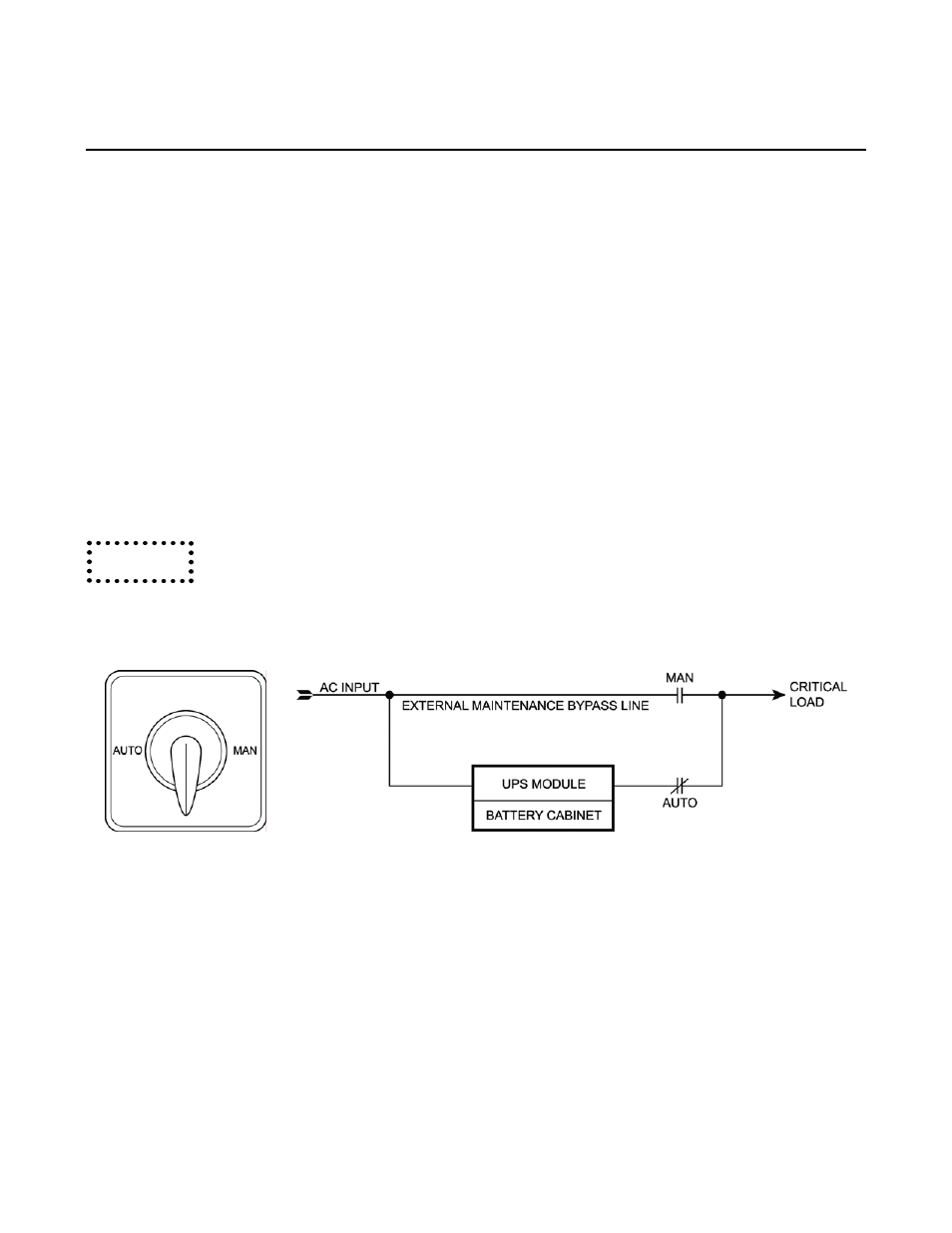
ILLUSTRATION 6-2: MAINTENANCE BYPASS SWITCH
The two Manual Bypass Switch Positions are:
1)
“MAN”
– Connects power to the critical load through the external maintenance bypass line.
UPS needs to be de-energized for maintenance purposes.
2)
“AUTO”
– Connects the critical load to the output of the UPS and establishes normal
operation.
Caution