Online power – OnLine Power Protector 3 User Manual
Page 26
OnLine Power
3-5
3.3.3 Customer Connections (Input and Output)
1)
Verify that the main input circuit breaker, battery circuit breaker, and output circuit breaker(s),
if provided, are in the ”OFF” position. See illustration 2-2 for the location of the circuit
breakers.
2)
Run the wire through the space between shelf and cabinet using provided knockouts.
3)
Connect the input wires to the input terminal block, TB10. Five (5) wires total: Phase A, Phase
B, Phase C, neutral, and ground.
• Connect Phase A, B, C.
1
2
3
4
Phase A
From
Reserve
Power
Input Source
Phase 2
Phase 3
Neutral or Ground for Delta connection
• Please refer to the functional diagram for Dual Input Power System Illustration 2-4
4)
Connect the output wires to the output terminal block, TB12. Five (5) wires total: Phase A,
Phase B, Phase C, neutral, and ground.
5)
Connect the battery wires from external battery cabinet (if provided) to battery terminal block,
TB6, three (3) wires total for (+), (-), and Ground.
This concludes the electrical connections.
Do not apply power to the Protector 3 at this time.
REFER TO BATTERY CONNECTION DIAGRAM
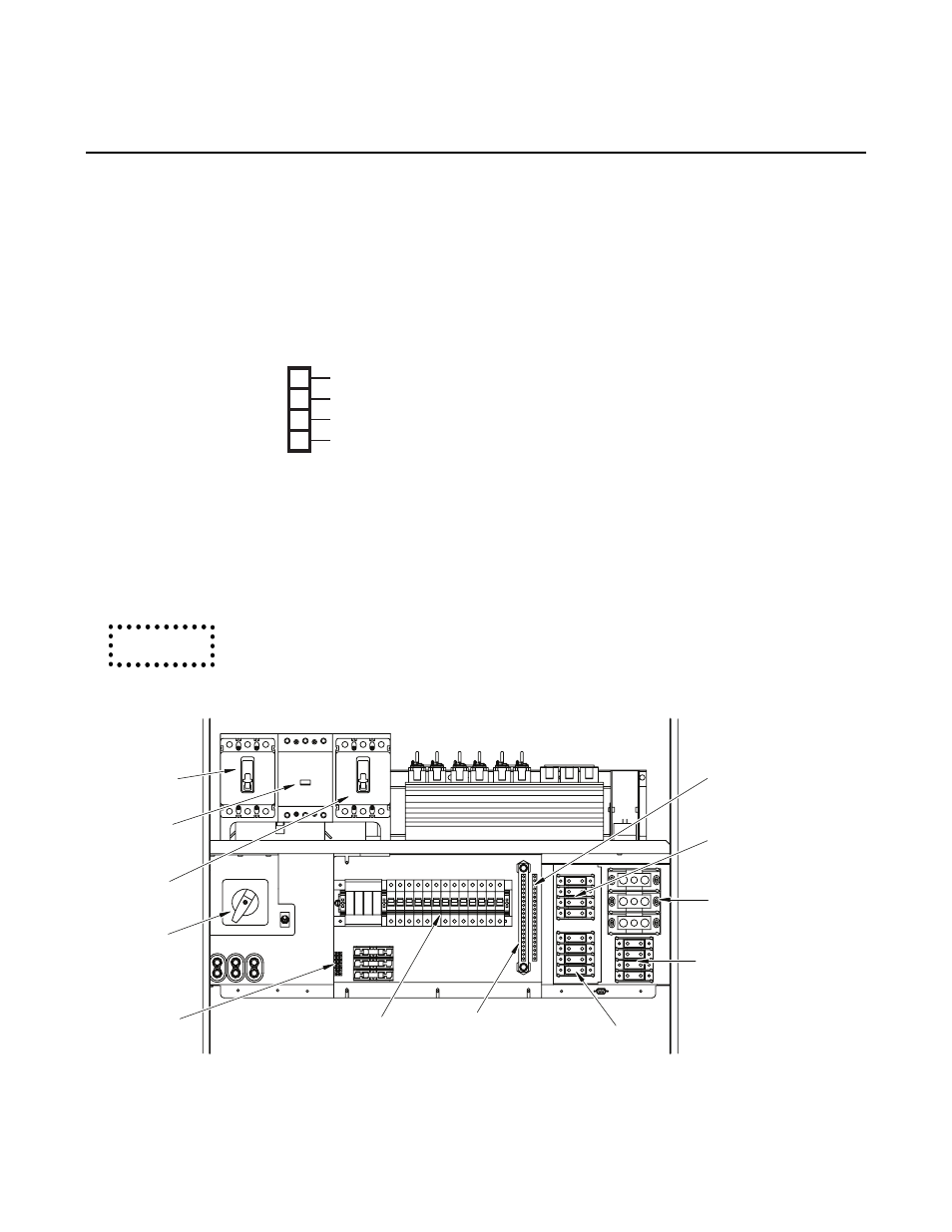
Maintenance
Bypass Switch
5 Form “C”
Alarm Terminal
Aux. Output
Circuit Breaker
Input C/B
Battery C/B
Output C/B
Ground TB
Netural Bus
Output TB
Input TB
Battery TB
Reserve Aux.
Input TB
(Optional)
ILLUSTRATION 3-3: Protector 3 Customer Connection
Caution