Online power – OnLine Power Protector 3 User Manual
Page 30
OnLine Power
4-2
• Verify that the LCD display panel indicates all correct parameters - see Appendix D for details.
• Verify that the output voltage is 120/208/277/480 VAC per the nameplate.
4.1.6 Close battery breaker in the UPS cabinet [and in battery cabinet(s)].
4.1.7
At this time, the Protector should be providing AC line power. If the Protector is not operating in the normal
mode, turn off the input circuit breaker. Contact OnLine Power at (800) 797-7782 for technical assistance.
4.1.8 Recheck that the output voltage is 208Y/120 or 480Y/277 VAC.
• If the output voltage is approximately the same as the nameplate, turn on the loads.
4.1.9 Verify battery operation and the inverter test switch.
• To place the Protector in battery operation (simulate loss of input power), press and hold yellow
Inverter Test Push Button. With Push Button in the hold position, the Protector should be running
on its internal batteries.
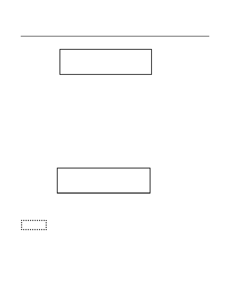
• Verify that the LCD panel displays is as below, where “xx” is the kVA of this unit:
UPS NORMAL @ xx kVA
INPUT BAD @ CHRGR ON
BATTERY OK @ DC OK
ON INVERTER @ OUT OK
Line 1
Line 2
Line 3
Line 4
• Release the yellow Inverter Push Button and Verify that the LCD PANEL displays
“INPUT OK @ CHRGR OFF”.
Be sure to release the Push Button, after the test, so it will not deplete the
batteries.
4.1.10
The Protector is now fully functional - providing clean, sine wave power to the load with battery back-up in
case of an input power failure.
This concludes the start-up procedures.
UPS NORMAL @ 15 kVA
INPUT OK @ CHRG ON
BATTERY OK @ DC OK
ON INVERTER @ OUT OK
Line 1
Line 2
Line 3
Line 4
Caution