Online power – OnLine Power Protector 3 User Manual
Page 17
OnLine Power
2-7
2.4.10 Inverter Test Switch
The Inverter Test Switch is a momentary push button for testing the Protector #3 and its batteries for
proper operation. With Protector 3 in operation, test switch is pushed and held, the unit will automatically
transfer to battery operation. The UPS will continue to run on batteries until the switch is released. Upon
release, the Protector 3 transfers back from battery to inverter and resumes normal operation.
2.4.11 DC Supply Transformer
The step down transformer, protected with fuse supplies DC rectifier which produces voltages for power
system boards. The primary of this transformer has various taps that need to be matched to the actual
main input voltages.
2.4.12 Maintenance bypass switch
This MBS can be used for maintenance when the inverter fails or PM is required. This MBS will transfer
the input power directly to critical load. Before switching the MBS to maintenance position, first turn on S1
(toggle switch), then switch to maintenance (MAN) position. Refer to the operation label on the unit. After
repair or PM, the MBS can be switched to UPS position. First turn-off S1 (toggle switch), then switch MBS
to UPS (AUTO) position.
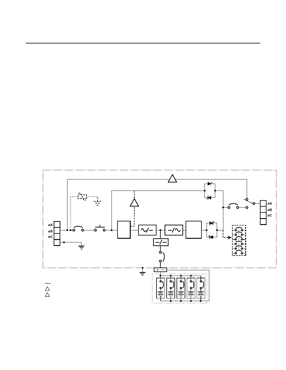
INPUT
CIRCUIT
BREAKER
TVSS
INPUT
CONTACTOR
Line removed when External Reserve Input Power is in use.
Optional
NOTE:
Optional External Wrap-around Bypass Switch is available.
1
2
3
4
BATTERY
CIRCUIT
BREAKER
BATTERY
CABINET
OUTPUT
STATIC
SWITCH
CIRCUIT
BREAKER
AUX OUTPUT CBs
TB10
INPUT
XFMR
INPUT
POWER
3 PHASE
1
2
3
4
TB11
INPUT
MAINT.
BYPASS
SWITCH
OUTPUT
POWER
3 PHASE
INVERTER
STATIC
SWITCH
1
Use for different Input and Output Voltage unit.
2
1
2
OUTPUT
XFMR
N
N
Batt.
Cab 1
Batt.
Cab 2
Batt.
Cab 3
Batt.
Cab 4
Batt.
Cab 5
ILLUSTRATION 2-4: FUNCTIONAL BLOCK DIAGRAM FOR SINGLE INPUT POWER