Online power, Illustration 4-1: heat sink assembly (fru) – OnLine Power Protector 3 User Manual
Page 32
OnLine Power
4-4
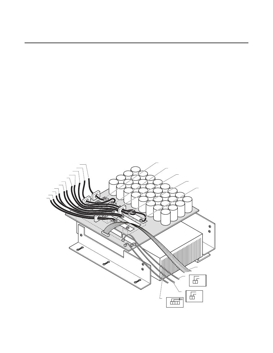
4.3.3 Heat Sink Assembly Replacement Procedure
1)
Disconnect and isolate all sources of power.
2)
The Heat Sink Assembly is located on the right side of the top electronic shelf, inside the UPS
cabinet (Illustration 4-1). Verify that all cables and connectors have labels and are identified
as shown. This is important for reinstalling the assembly.
3)
Disconnect connectors P7, P6, P4, P1 from the PCB, A1, which is mounted horizontally on the
big black heat sink.
4)
Disconnect 11 power cables at TB4-1 through TB4-7B using flat screw driver. Verify and
install label ID for each cable before disconnecting.
5)
Loosen 3 Phillips head screws at front holding heat sink bracket. Pull the complete assembly
forward and up. Remove it from tray gently, making sure that no cables or wires are catching
(See illustration 4-1).
6)
Install the new assembly in the reverse order. Note that the rear bracket attached to the heat
sink slides under the bracket secured on to the back panel. Slide the assembly back and
reinstall 3 Phillips screws.
7)
Reinstall all the cables and connectors in the reverse order. Verify per illustration 4-1.
8)
Verify connections prior to starting up the unit.
1
J7
P6
P4
P7
P1
TB4-1
TB4-2
TB4-3
TB4-4
TB4-2
TB5-2
1
1
1
J1
J7
J6
J6
1 2 3 4
J4
1 2
BLK
RED
J7
1 2
BLK
RED
Phase C (Q3/Q4)
Phase A (Q1/Q2)
Phase B (Q5/Q6)
E1/C2 (Q7/Q8)
E2 (Q7/Q8)
TB4-4B
TB4-5B
TB4-6B
TB5-1
TB4-7B
ILLUSTRATION 4-1: HEAT SINK ASSEMBLY (FRU)