Online power – OnLine Power Protector 3 User Manual
Page 47
OnLine Power
6-8
6.12 OPTIONAL DUAL INPUT SYSTEM WYE/WYE – SAME INPUT/OUTPUT VOLTAGE
P/N Voltage
9100-1446-01
208V IN/OUT 10/15/20 kVA,
480V IN/OUT 10-50 kVA
9100-1446-02
208V IN/OUT 25/30/40 kVA
9100-1446-03
208V IN/OUT 50 kVA
6.13 OPTIONAL DUAL INPUT SYSTEM DELTA/WYE – SAME INPUT/OUTPUT VOLTAGE
P/N Voltage
9100-1446-04
208V IN/OUT 10/15/20 kVA,
480V IN/OUT 10-50 kVA
9100-1446-05
208V IN/OUT 25/30/40 kVA
9100-1446-06
208V IN/OUT 50 kVA
6.14 OPTIONAL DUAL INPUT SYSTEM DELTA/DELTA –DIFFERENT INPUT/OUTPUT VOLTAGE
6.14.1Delta Input System 208V IN / 480V OUT Wye-Wye
Use 6.13 and 6.14 Dual Input System and separate Iso-Care Transformer to match the output voltages.
Consult factory for proper kVA and model number
6.15 OPTIONAL SEISMIC MOUNTING BRACKET – P/N 9100-1317-02
P/N: 5088-025
Left / Right seismic floor mounting bracket
6.16 OPTIONAL STACKABLE RACK – P/N 9100-1429-xx
Drawings: 6001-032-07 Refer to illustration on page B-8. One rack only
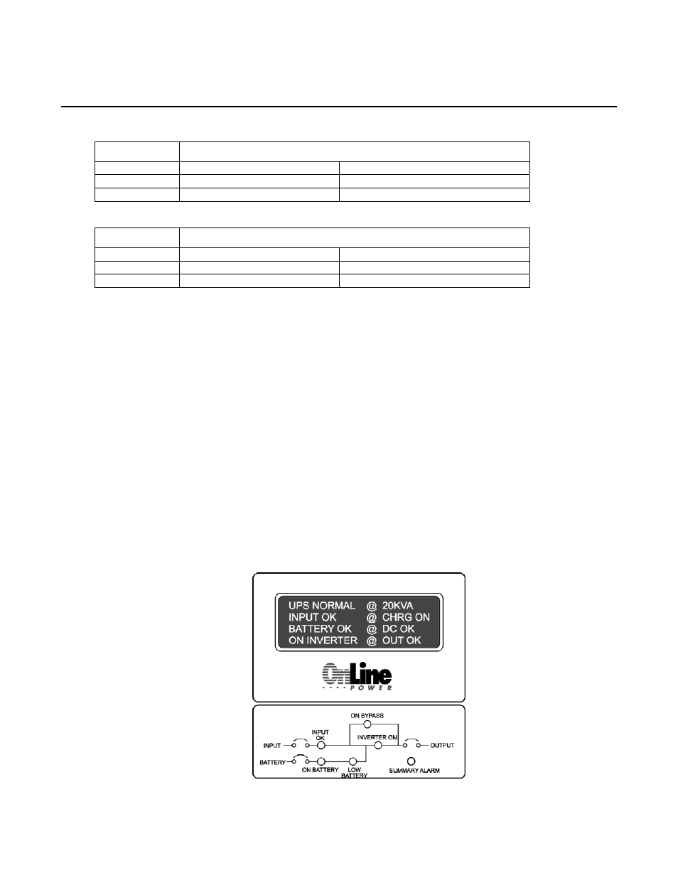
6.17 OPTIONAL POWER FLOW MIMIC – P/N 9100-1493-02 (illustration 6-3)
6.17.1 Operation
Power Flow Mimic allows unit power status verification at-a-glance. It has 6 LED’s indicating the following
conditions: GREEN – Input OK, GREEN – Inverter On, YELLOW – On Battery, YELLOW – On
Bypass, RED – Low Battery, RED – Summary Alarm. The LED’s are located on the pictogram below for
quick status assessment.
ILLUSTRATION 6-3: MIMIC PAD