Vav/cav controller setpoints, Vav/cav setpoint screens, Vav/cav/mua operator interface sd – Orion System VAV II Controller v.1 User Manual
Page 35
VAV/CAV/MUA Operator Interface SD
VAV/CAV CONTROLLER SETPOINTS
35
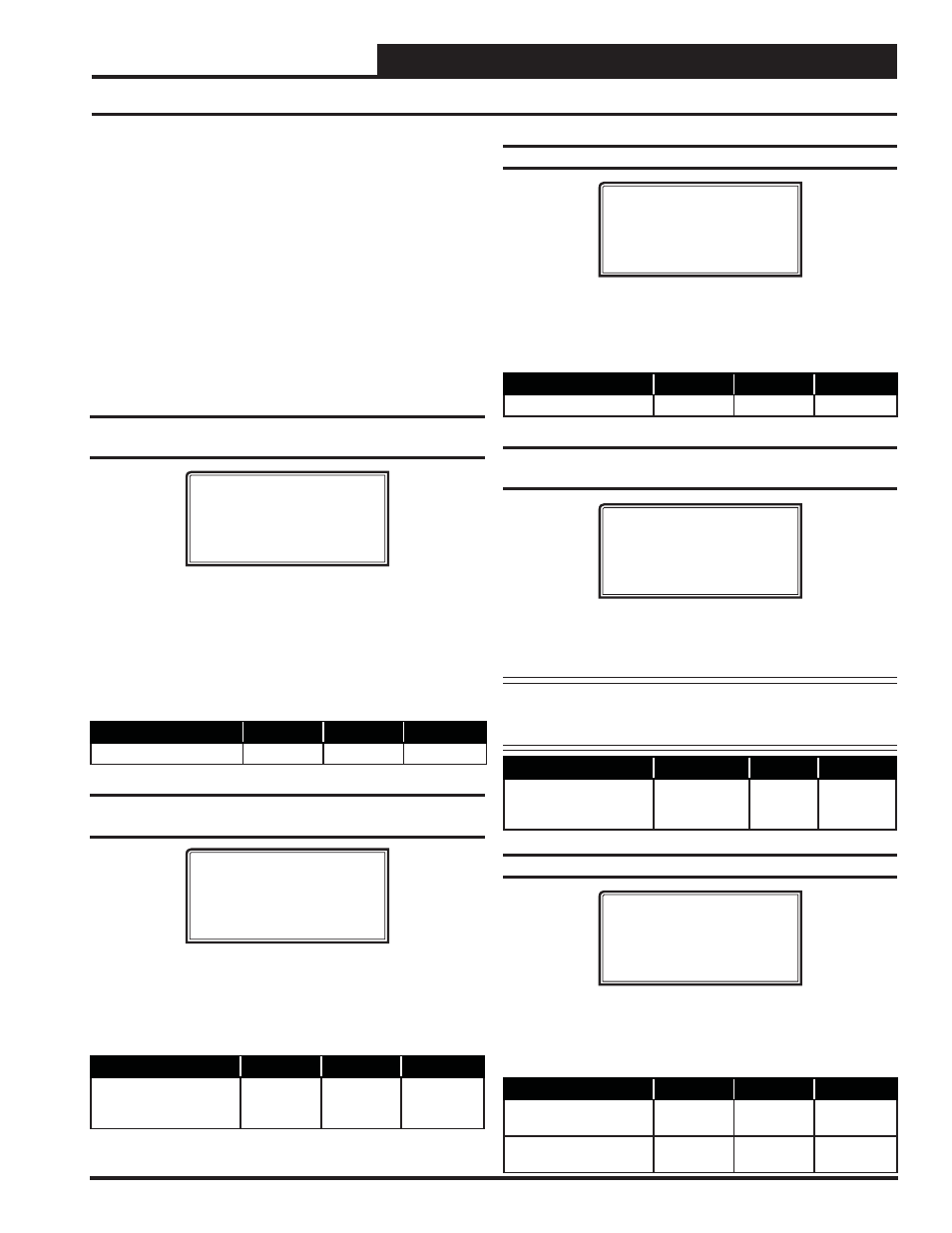
Setpoint Screen #21 - HVAC Schedule
VAV/CAV Spts ID 0001
AHU Schedule By
Schedule Number: 0
0=AHU 1-7=Scheduler
Normally, the AHU will use its own internal time clock and week
schedules to set the Occupied Mode of operation. If you have several
air handlers, you can connect an external scheduling device to the com-
munications loop and program the air handler for the desired schedule to
follow. If the AHU is using its internal schedule, enter
<0>
for Internal.
Description
Minimum
Default
Maximum
Schedule Number
0
0
1 to 7
Setpoint Screen #22 - Economizer Maximum
Position if High CO
2
Level
VAV/CAV Spts ID 0001
Maximum Economizer
Position if High CO2
Level Occurs.: 100%
If you have confi gured the air handler to read a CO
2
Sensor, it will over-
ride the Minimum Economizer Position up to this position if the CO
2
level rises above its setpoint by the adjustable Reset Range amount. See
Setpoint Screen #23.
NOTE:
The Minimum Position is determined by the user-
adjustable Min Position Setpoint on Setpoint Screen #14
on page 34.
Description
Minimum
Default
Maximum
Maximum Economizer
Position If High CO
2
Level Occurs
Economizer
Minimum
Position
100%
100%
Setpoint Screen #23 - CO
2
Protection Limit
VAV/CAV Spts ID 0001
CO2 Protection Limit
Max Level: 900 PPM
Reset Range: 100 PPM
If you confi gure the air handler to read a CO
2
Sensor, the Max Level is the
point at which the Economizer Minimum Position starts to reset upward.
As the CO
2
level rises above the Max Level by the Reset Range amount,
the Economizer will have reset its Minimum Position proportionally up
to the previously defi ned Economizer Maximum Position in High CO
2
.
Description
Minimum
Default
Maximum
CO
2
Protection Limit
Max Level
0 PPM
900 PPM
5000 PPM
CO
2
Protection Limit
Reset Range
0 PPM
100 PPM
1000 PPM
VAV/CAV Setpoint Screens
VFD Percentage Cool Reset Example:
Hi Reset = 70%
SAT Setpoint (Spt) = 55°F
Lo Reset = 30%
SAT Setpoint (Rst) = 65°F
VFD Percentage Heat Reset Example:
Hi Reset = 30%
SAT Setpoint (Spt) = 90°F
Lo Reset = 70%
SAT Setpoint (Rst) = 120°F
Input Voltage Cool Reset Example:
Hi Reset = 0 Volts
SAT Setpoint (Spt) = 55°F
Lo Reset = 10 Volts
SAT Setpoint (Rst) = 65°F
Input Voltage Heat Reset Example:
Hi Reset = 0 Volts
SAT Setpoint (Spt) = 90°F
Lo Reset = 10 Volts
SAT Setpoint (Rst) = 120°F
Setpoint Screen #19 - Supply Fan Starting
Delay Timer
VAV/CAV Spts ID 0001
Start Fan Delay
Timer...: 999s
[999= Unit Addr x 5]
This is the amount of time that the main HVAC unit fan will delay before
starting after an occupied signal is initiated or after a power failure. The
default value is 999. With the default value, the delay will be equal to
the unit address multiplied by 5.
Example: Controller ID (address) 18 would cause a 90 second delay
when the default value of 999 is used. Controller ID (address) 30 would
cause a 150 second delay when the default value of 999 is used.
Description
Minimum
Default
Maximum
Fan Start Delay Timer
0 Sec
999 Sec
999 Sec
Setpoint Screen #20 - Mechanical Heat/Cool
Failure Time Period
VAV/CAV Spts ID 0001
Mechanical Heat/Cool
Failures Occur After
No Change In 15Min
When Heating or Cooling Mode is initiated and staging is activated, if the
Supply Air Temperature does not rise or fall 5°F within the Mechanical
Heat/Cool Failures Occur After No Change In Setpoint time period, a
Mechanical Heating or Cooling Failure Alarm will be generated. The
alarm is for status reporting only. The HVAC unit will continue to run.
Description
Minimum
Default
Maximum
Mechanical Heat/Cool
Failures Occur After
No Change In
0 Min
15 Min
300 Min