Vav/cav controller status, Vav/cav status screens, Vav/cav/mua operator interface sd 40 – Orion System VAV II Controller v.1 User Manual
Page 40
VAV/CAV CONTROLLER STATUS
VAV/CAV/MUA Operator Interface SD
40
VAV/CAV Status Screens
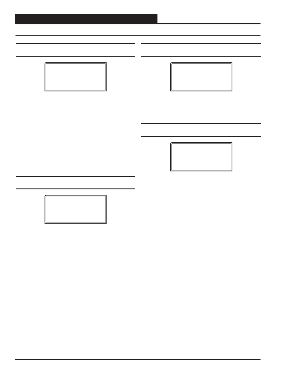
Status Screen 5 - Outdoor Air Temperature &
Humidistat
VAV/CAV v 1.00 0001
Outdoor Air: XX.XºF
Humidistat Open
Line 2 Current Outdoor Air Temperature
If an Outdoor Air Temperature Sensor has been installed
and
confi gured on the unit or if an Outdoor Air Broadcast
has
been
confi gured on another Unit Controller on the
system, the Outdoor Air Temperature will appear on
this line. If not, this line will display a temperature that is
half way between the Cooling and Heating Lockout
Setpoints.
Line 3 Current Outdoor Air Relative Humidity
If an Outdoor Humidity Sensor has been installed and
confi gured on the Unit Controller, the Outdoor Air
Relative Humidity Percentage will appear on this line.
If not, this line will display 0%.
Status Screen 6 - Supply Air Temperature &
Setpoint
VAV/CAV v 1.00 0001
Supply Air.: XX.XºF
Return Air.: XX.XºF
Supply Spt.: XX.XºF
Line 2 Current Supply Air Temperature
The Supply Air Temperature is always required. If a
Supply Air Temperature Sensor is not installed, the
controller will not operate correctly and will display 0°F.
Line 3
Current Active Return Air Setpoint
This is the Return Air Setpoint for the mode that the
unit is currently operating in.
Line 4
Current Active Supply Air Setpoint
This is the Supply Air Setpoint for the mode that the
unit is currently operating in. If the Supply Air Reset is
confi gured, this is the calculated setpoint based on the
current Reset Source conditions. Can be reset from an
external signal if this option is selected.
Status Screen 7 - Static Pressure, Fan VFD,
and Economizer
VAV/CAV v 1.00 0001
Static Pr.: 0.00”
Fan VFD...: 0%
Economizer: 0%
Line 2
Current Static Pressure Reading
Line 3
Current Fan VFD Signal Percentage
Line 4
Current Economizer Damper Percentage Open
Status Screen 8 - Relief Pressure and Relief
VFD
VAV/CAV v 1.00 0001
Relief Pr.: 0.00”
Relief VFD.: 0%
[Relief is Optional]
Line 2
Current Relief Pressure
If the unit is confi gured for Relief Pressure Control.
This will display 0.00” if you don’t control Relief Pressure.
Line 3
Current Relief Fan VFD Signal.
This will display 0% if the unit is not confi gured for Relief
Pressure
Control.
Line 4
Just a reminder that this is an optional control output
and may or may not have live data to display.