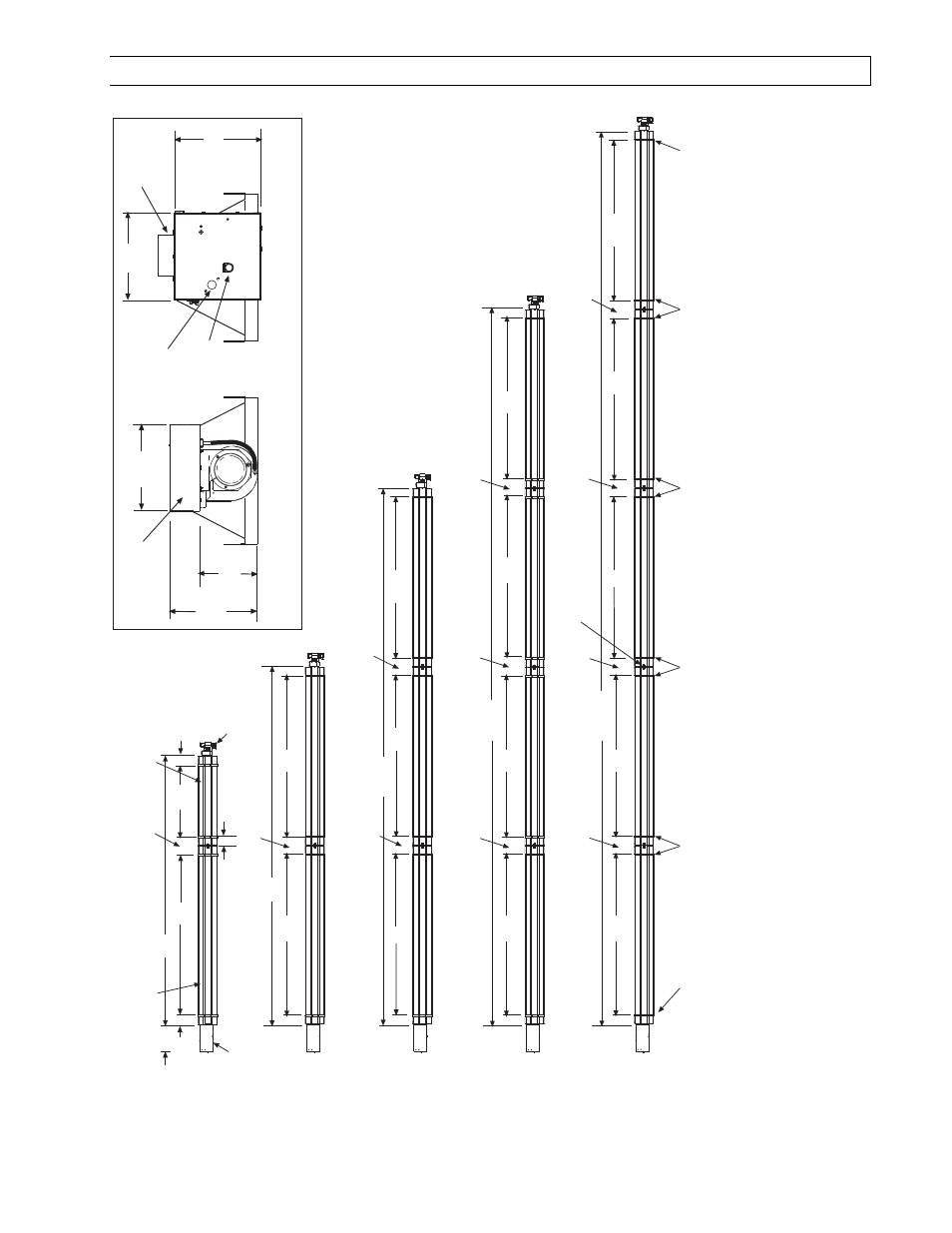
1) lts series dimensions, Typical dimensions up to 50 ft. shown – Space Ray LTS Series Two Stage User Manual
Page 21
Form #43155040
-20-
May 2013
11.1)
LTS SERIES DIMENSIONS
Typical Dimensions Up to 50 Ft. Shown
Models: LTS 40, 50
Models: LTS 60, 75
Models: LTS 80, 90, 100, 1
10, 120,
125, 130
360
(914cm)
108
(274cm)
12
(30cm)
12
(30cm)
180
(457cm)
108
(274cm)
12
(30cm)
48
(122cm)
5 FT Body Section
108
(274cm)
108
(274cm)
4
T
ube Coupling
(typical)
Models: LTS 140, 150, 160, 175
18
(46cm)
Control Box
Draf
t
Inducer
10 Ft. Body Section (typical)
Bottom V
iew
13
T
ube Support/
Hanger Bracket
108
(274cm)
12
(30cm)
240
(610cm)
108
(274cm)
108
(274cm)
600
(1524cm)
108
(274cm)
108
(274cm)
108
(274cm)
108
(274cm)
12
(30cm)
12
(30cm)
12
(30cm)
12
(30cm)
12
(30cm)
108
(274cm)
480
(1219cm)
108
(274cm)
12
(30cm)
108
(274cm)
108
(274cm)
12
(30cm)
Models: LTS 180, 200, 225, 250
13
T
ube Support/
Hanger Bracket
7
(18cm)
10-7/8 (28cm)
10-9/16 (27cm)
8-1/2 (22cm)
LTS (draf
t inducer end view)
LTS (control box end view)
Junction Box (electric supply)
8-1/2 (22cm)
Sight Glass
1/2 MPT
Gas
Connection
Optional Fresh
Air Inlet
6
(15cm)
6
(15cm)
6
(15cm)
13
T
ube Support/
Hanger Bracket
13
T
ube Support/
Hanger Bracket
13
T
ube Support/
Hanger Bracket
13
T
ube Support/
Hanger Bracket
Note: there is 1/2 overlap between Control Box and the first tube. Thus af
ter inst
allation, the dist
ance is 5-1/2 between control box
and the first
T
ube Support/Hanger Bracket.