Space Ray LTS Series Two Stage User Manual
Page 60
Form #43155040
May 2013
-59-
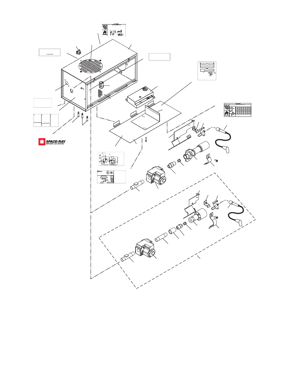
CONTROL BOX
COMPONENTS
57
58 41
55
56
63
62
51,51a,
52,52a
53
45
76
10
61
59
47
43
60
54
44
53
51,52
74
67
68
69
70
71
72
73
41
40-75M BTU UNITS
ONLY
SCHEMATIC WIRING DIAGRAM
MOT
Motor
Moteur
GL
Green Light
Témoin vert
TRANS 24V Transformer
Transformateur 24ÊV
RL
Red Light
Témoin rouge
AS
Air Switch
pressostat
SM
Ignition Module
Bloc d'allumage
IG/S
Ignitor / Sensor
électrode
V
Gas Valve
Robinet à gaz
AL
Amber Light
Témoin ambre
MOT
120V
GL
TRANS
RL
AS
IG/S
AL
V
SM
42785000 Rev. C 10/04
25V GND
25V
75
42874000 Rev. G 10/04
G
BL
BL
BK
BK
R
W
BK
BK
R
BK
W
BK
BK
W
DRAFT
INDUCER
MOTOR
GAS VALVE
AIR SWITCH
TRANSFORMER
120V PRIMARY
24V SECONDARY
A
G
R
IGNITION MODULE
HIGH VOLTAGE
CABLE
ELECTRODE
GAP 3/16
CONTINUE TO
ADDITIONAL
HEATERS
NEUTRAL
120V
THERMOST
A
T
GROUND
L1
L2
TERMINAL
BLOCK
FACTORY WIRING
FIELD WIRING
CONNECTION WIRING DIAGRAM
CONTROL CABINET
If any of the original wire as supplied with the
appliance must be replaced. It must be
replaced with wiring material having a
temperature rating of at least 105oC. (18
AWG. - UL / CSA 600V Type TEW)
When connecting the supply circuit to the
heater, wiring material having a minimum size
of 14 AWG and a temperature rating of at
least 90oC shall be used.
WIRE LEGEND
ENGLISH
FRANCAIS
BK
BLACK
NOIR
W
WHITE
BLANC
R
RED
ROUGE
BL
BLUE
BLEU
G
GREEN
VERT
A
AMBER
AMBRE
MONITORING LIGHTS
GND
(BURNER)
25V
(GND)
25V
VALVE VALVE
FUSE 2A
JUNCTION BOX
SJO CABLE
(NOT
INCLUDED)
W
R
BK
Schéma de circuit de connexion
Circuit d'origine
Connexions client
Lampes témoins
Neutre
Terre
Vers les autres
radiateurs
Plaque à
bornes
Transformateur
bobine primaire 120ÊV
bobine secondaire 24ÊV
pressostat
Robinet à gaz
Écartement
d'électrode
4,7Êmm
Haute tension
Armoire de commande
Bloc d'allumage
Moteur
d'amorce
d'aspiration
S'il faut remplacer un fil de l'appareil d'origine,
utiliser exclusivement des fils à température
de service nominale d'au moins 105C (18
AWG. - UL / CSA 600ÊV
Type TEW).
Pour raccorder le circuit d'alimentation au
radiateur, utiliser des fils de calibre 14 AWG
ou plus à température de service nominale
d'au moins 90C.
Fusible
Bloc de jonction
Câble SJO
(non compris)
WARNING: Improper
installation, adjustment,
alteration, service or
maintenance can cause
property damage, injury
or death. Read the
Installation, Operating
and Maintenance
Instruction thoroughly
before servicing this
equipment.
AVERTISSEMENT: Une
installation, un réglage, une
modification, une réparation
ou un entretien incorrect peut
entraîner des dommages
matérials, des blessures ou
la mort. Lisez attentivement
les instructions dinstallation,
de fonctionnement et
dentretien avant de procéder
à linstallation ou à lentretien
de cet équipment.
WARNING: If not
installed, operated and
maintained in accordance
with the manufacturers
instructions, this product
could expose you to
substances in fuel or from
fuel combustion which can
cause death or serious
illness and which are
known to the State of
California to cause cancer,
birth defects or other
reproductive harm.
WARNING: This product
contains a chemical known
to the state of California to
cause cancer.
This heater can be
installed in various
configurations as shown
in the heater layout
section of the instructions
42875000 Rev. E 10/04
77
24 VOLT SUPPLY
ONLY!
4326900-0
Rev. A
78
TERMINAL
1 2
43270000
Rev. A
79
80
GAS TYPE
SUPPLY PRESSURE
Pression de Sortie
Type de Gaz
MAXIMUM
MINIMUM
MANIFOLD PRESSURE
Pression a lechappement
INPUT Btu/Hr
Consommation Btu / Hr
ORIFICE SIZE
Dimensions bec Veilleuse
MODEL NO.
No. de Modelè
Installation in:
1. Aircraft hangars must be in accordance with the standard for Aircraft Hangars.
ANSI/NFPA 409 (latest edition).
2. Public garages must be in accordance with the standard for parking structures,
ANSI/NFPA 88a (latest edition), or with the standard for repair garages,
ANSI/NFPA 88b (latest edition)
SERIAL NO.
No. de Série
LIGHTING & SHUTDOWN INSTRUCTIONS
1. Turn on gas & electrical supply.
2. Set thermostat to call for heat.
3. Ignition should occur after prepurge.
4. If ignition fails, the unit will spark for approximately 21 seconds
& go into safety lockout. Turn thermostat (or power) off for 60
seconds to take out of lockout.
5. If heater does not light, shut off gas completely for 5 minutes
before attempting to relight.
6. To shut down the heater, turn off the gas & electrical supply.
Infrared Radiant Tube Heater
Radiateur à tuve rayonnant à infrarouge
Gas Fired products Inc. Charlotte, NC
INSTRUCTIONS DALLUMAGE ET DE FERMETURE
1. mettre la valve a gaz et linterrupteur a ON.
2. Creer une demande de chauffage au thermostat.
3. Lallumage devrait se produire apres de prepurge.
4. Si lallumage ne se fait pas, le controle dallumage continu de
produire des etincelles sur une periode de 21 sec. et ensuite
tomber en securite. Mettre le thermostat (ou le courant) en
position darret (OFF) pour une periode de 60 sec. a fin
dinterrompre le processus de securite.
5. Si lappareil ne sallume pas, fermez le gaz completement pour
une period de 5 min. avant deffectuer une nouvelle tentative
dallumage.
6. Pour fermer lappareil, fermez le gaz et le courant electrique.
For indoor installation only
Installer à lintérieur seulement
Vented or Unvented
ELECTRICAL:
ALTITUDE
ANSI Z83.20 / CSA 2.34 - 2008
Tel: 1800 438 4936 e-mail [email protected]
CODE DATE
42848000 Rev. K 1/09
MAX ANGLE:
Max Angle
Electrique
81
Combustible material must be located outside the clearance dimensions listed.
Ceiling Clearance is 12 (30cm) when installed in an UNVENTED configuration. Ceiling
clearance is 18 (46cm) when the optional corner reflectors are not used on ETS or LTS.
Failure to do so may result in death, serious injury or property damage
Models LTS/LTU/ETS/ETU
43344000 Rev. B 10/04
Le dégagement au-dessus de l'appareil doit être d'au moins 30 cm quand l'appareil est installé
SANS ÉCHAPPEMENT.
Le dégagement au-dessus de l'appareil doit être d'au moins 46cm
quand les réflecteurs d'angle optionnels ne sont pas utilisés sur l'ETS ou le LTS.
D
D
Dessous, 6m du brûleur
Below 20ft from burne
r
C*
20ft (6m)
Model No
A
B
C
D
E
F
C*
40,50
27
6
40
30
48
12
-
(69cm)
(15cm)
(104cm)
(76cm)
(122cm)
(30cm)
60,75
27
6
60
30
48
12
-
(69cm)
(15cm)
(145cm)
(76cm)
(122cm)
(30cm)
80,90
52
6
84
30
52
12
72
(132cm)
(15cm)
(145cm)
(76cm)
(122cm)
(30cm)
(183cm)
100
66
6
88
40
66
20
72
(168cm)
(15cm)
(224cm)
(102cm)
(168cm)
(30cm)
(183cm)
110,120,
66
6
101
40
66
20
72
125,130
(168cm)
(15cm)
(257cm)
(102cm)
(168cm)
(51cm)
(183cm)
140,150,
84
6
106
48
84
24
72
160,175
(213cm)
(15cm)
(269cm)
(122cm)
(213cm)
(61cm)
(183cm)
180,200,
84
18
132
48
84
24
72
225,250
(213cm)
(46cm)
(335cm)
(122cm)
(213cm)
(61cm)
(183cm)
Horizontal
B
C
A
A
45 degrees
B
C
E
F
Montage horizontal
Montage à 45°
82
Alternate Supply
Locations
TYPICAL GAS
CONNECTION
END VIEW
Movement
14 - 17
(356 - 432mm)
Control Box
SIDE VIEW
Flexible Connector
Optional Second Stage Regulator with
Vent Leak Limiter if required to reduce
the Supply Pressure below 14 W.C.
Recommended Gas
Pressure 2 PSIG
Gas Supply
Piping
Sediment Trap
(Drip Leg)
43344050 Rev. C 3/09
Install the gas flexible hose as shown in the diagram below:
Sharp bends, kinks, twists and tension in the hose may cause failure resulting in a gas
leak.
Failure to follow these instructions may result in death, serious injury or property damage.
83
43a
46
84
42
42
Two Stage
43269070 4/08
High Fire
Low Fire