4) lts series heater assembly – Space Ray LTS Series Two Stage User Manual
Page 23
Form #43155040
-22-
May 2013
11.3)
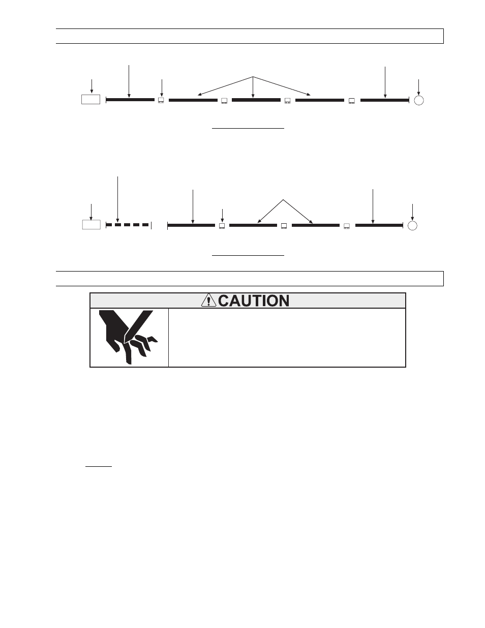
LTS 180-250 SERIES HEATER ASSEMBLY OVERVIEW
Control Box
Aluminized Calorized Steel Tube (ALC)
(with one 12 radial hole Flange)
Tube Coupling
Aluminzed Calorized Steel Tube (ALC)*
Aluminized Calorized Steel Tube (ALC)
(with one 12 radial hole Flange)
Draft Inducer
50 FT
Shown
* Additional tubes of this type are added to increase the heater length up to a maximum of 80 ft.
Models:
Models:
Models:
Models: LTS
LTS
LTS
LTS 180
180
180
180----2
2
2
20
0
0
00
0
0
0
Control Box
Alumi-Therm Calorized Steel Tube (ATC)
(with two 6-hole Flanges)
Tube Coupling
Aluminized Calorized Steel Tube (ALC)*
Aluminized Calorized Steel Tube (ALC)
(with one 12 radial hole Flange)
Draft Inducer
50 FT
Shown
* Additional tubes of this type are added to increase the heater length up to a maximum of 80 ft.
Aluminized Calorized Steel Tube (ALC)
(with one 12 radial hole Flange)
Models: LTS 225
Models: LTS 225
Models: LTS 225
Models: LTS 225----250
250
250
250
11.4)
LTS SERIES HEATER ASSEMBLY
Sheet metal parts, particularly reflectors and vent have sharp
edges. Always use gloves when handling.
Failure to do so may result in death, serious injury or property
damage.
CUT HAZARD
During field assembly of the LTS series heater body sections, the recommended procedure is as follows:
1.
Before hanging heater sections, first determine the actual layout of the system (see Sections 11.0) &
11.1) for details). Consideration must also be taken for flue pipe, fresh air ducting, gas piping, clearances
to combustibles, etc. before hanging heater.
2.
Put the suspension in place using proper suspension method (see Section 5.0).
3.
Hang each tube section individually. Observe the following requirements.
a)
DO NOT
DO NOT
DO NOT
DO NOT attach the heater tube sections together on the ground and attempt to hang the entire system.
The weight of the individual heater body sections can cause misalignment and
The weight of the individual heater body sections can cause misalignment and
The weight of the individual heater body sections can cause misalignment and
The weight of the individual heater body sections can cause misalignment and damage to the heater.
damage to the heater.
damage to the heater.
damage to the heater.
b)
DO NOT
DO NOT
DO NOT
DO NOT relocate the tube support/hanger brackets, especially at the control end of the heater.
relocate the tube support/hanger brackets, especially at the control end of the heater.
relocate the tube support/hanger brackets, especially at the control end of the heater.
relocate the tube support/hanger brackets, especially at the control end of the heater.
c)
For LTS40-200 Models, the first tube section MUST
MUST
MUST
MUST be a 10 ft. tube with one 12-radial hole flange which
is to mount control box.
d)
For LTS225-250 Models, the first tube section MUST
MUST
MUST
MUST be a 10 ft. tube with two 6-hole flanges.
e)
For all LTS models, the last tube section MUST
MUST
MUST
MUST be an either 10 ft. or 5 ft. tube with one 12-radial hole
flange which is to mount draft inducer.
f)
Failure to attach the cont
Failure to attach the cont
Failure to attach the cont
Failure to attach the control box to the flange end as indicated above will void the manufacturer’s
rol box to the flange end as indicated above will void the manufacturer’s
rol box to the flange end as indicated above will void the manufacturer’s
rol box to the flange end as indicated above will void the manufacturer’s
warranty.
warranty.
warranty.
warranty.
g)
Any S hook used in suspension should be crimped close.