0) electrical connections, Electric shock hazard – Space Ray LTS Series Two Stage User Manual
Page 36
Form #43155040
May 2013
-35-
16.0)
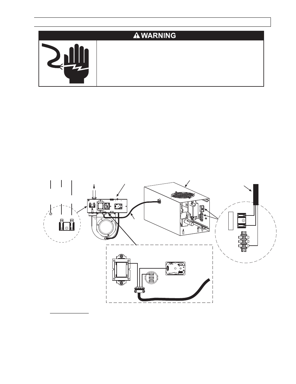
ELECTRICAL CONNECTIONS
Failure to do so may result in death or serious injury.
This appliance must be connected to a properly grounded electrical source.
Disconnect electrical power and gas supply before servicing.
ELECTRIC SHOCK HAZARD
1.
All electric wiring shall conform to the latest edition of the National Electrical Code (ANSI/NFPA No. 70),
or the code legally authorized in the locality where the installation is made.
2.
The unit must be electrically grounded in accordance with the National Electrical Code (ANSI/NFPA No.
70-latest edition). In Canada, refer to current standard C22.1 Canadian Electrical Code Part 1.
3.
The wiring providing power to the heater shall be connected to a permanently live electrical circuit, one
that is not controlled by a light switch.
4.
The power supply to the unit should be protected with a fused disconnect switch or circuit breaker. A
service switch, as required by local codes, shall be located in the vicinity of the heater (check local codes
for allowable distances) and should be identified as Heater Service Switch. All electrical wiring must be
located in accordance with the required Clearances to Combustibles from the heater as listed on the
nameplate on the heater.
5.
When connecting the supply circuit
supply circuit
supply circuit
supply circuit to the heater, wiring material having a minimum size of 14 AWG and
a temperature rating of at least 90°C shall be used.
Ground
Screw
Terminal
Block
L2
L1
INCOMMING
POWER SUPPLY
CONNECTION
GROUND
NEUTRAL
120V
1
2
Terminal
Terminal
Block
SJO Cable
Viewed From
Inside
Draft Inducer
Junction Box
Control
Box
24V
SJO
Cable
Terminal Block
(to gas valve)
HI
L2
L1
Motor
LO
C
HI
Transformer
24V
C
Air Switch
Terminal
Block
SJO Cable
HI
L2
L1
6.
LTS
LTS
LTS
LTS SERIES ONLY:
SERIES ONLY:
SERIES ONLY:
SERIES ONLY: The installer will provide type 3 core SJO cable having minimum size of 18 AWG to
connect between the draft inducer junction box and the control box. See wiring diagram below. Secure
with 3/8” connectors as previously described in the attachment of the control box and draft inducer.
Connect wire leads as shown in the Connection Wiring Diagram. The SJO cable should be located and
secured to protect it from mechanical damage.