Internal connection wiring diagra, Schematic – Space Ray LTS Series Two Stage User Manual
Page 37
Form #43155040
-36-
May 2013
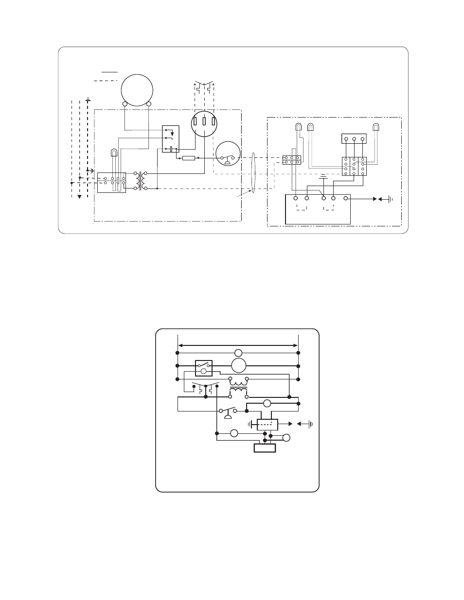
INTERNAL CONNECTION WIRING DIAGRA
INTERNAL CONNECTION WIRING DIAGRA
INTERNAL CONNECTION WIRING DIAGRA
INTERNAL CONNECTION WIRING DIAGRAM
M
M
M —
—
—
—
Direct Spark Ignition
Direct Spark Ignition
Direct Spark Ignition
Direct Spark Ignition
Écarteme
nt
d'électrod
e 4,7Êmm
Haute tension
Armoire de commande
Green
Amber
Light
(LO Fire)
Red
Light
HIGH
VOLTAGE
CABLE
ELECTRODE
GAP 3/16
CONTROL CABINET
White
Red
C
HI
LO
2-STAGE
GAS VALVE
TERMINAL
BLOCK
White
Blue
Amber
Light
(HI Fire)
L1
L2
Black
Black
Red
Red
Black
White
Black
Black
White
DRAFT
INDUCER
MOTOR
TRANSFORMER
120V PRIMARY
24V SECONDARY
Green
Light
CONTINUE
TO
ADDITIONAL
HEATERS
NEUTRAL
120V
GROUND
L1
L2
TERMINAL
BLOCK
JUNCTION BOX
Neutre
Terre
Vers les autres
radiateurs
Plaque à
bornes
Transformateur
bobine primaire 120ÊV
bobine secondaire 24ÊV
Moteur
d'amorce
d'aspiration
Bloc de jonction
1
5
3
4
RELAY
AIR
SWITCH
pressostat
3 WIRE
CABLE
(NOT INCLUDED)
White
FUSE 2A
Fusible
C
LO
HI
2-STAGE
THERMOSTAT
C
LO
HI
Black
Red
42874040 Rev. A 1/2012
Robinet à gaz
(non compris)
CONNECTION WIRING DIAGRAM
Schéma de circuit de connexion
If any of the original wire as supplied with the
appliance must be replaced. It must be
replaced with wiring material having a
temperature rating of at least 105oC. (18
AWG. - UL / CSA 600V Type TEW)
When connecting the supply circuit to the
heater, wiring material having a minimum size
of 14 AWG and a temperature rating of at
least 90oC shall be used.
S'il faut remplacer un fil de l'appareil d'origine,
utiliser exclusivement des fils à température
de service nominale d'au moins 105C (18
AWG. - UL / CSA 600ÊV
Type TEW).
Pour raccorder le circuit d'alimentation au
radiateur, utiliser des fils de calibre 14 AWG
ou plus à température de service nominale
d'au moins 90C.
Connexions client
FACTORY WIRING
FIELD WIRING
Circuit d'origine
TERMINAL
BLOCK
Plaque à
bornes
P l a q u e à
b o r n e s
Black
TERMINAL
BLOCK
P l a q u e à
b o r n e s
Black
White
Blue
Y
ellow
Relais
IGNITION MODULE
GND
(BURNER)
25V
Bloc d'allumage
VALVE
VALVE
NOTES:
NOTES:
NOTES:
NOTES:
1.
If any of the original wire as supplied with the appliance must be replaced, it must be replaced with
wiring material having a temperature rating of at least 105ºC. (18 Ga. CSA 600V Type TEW)
2.
When connecting the supply circuit to the heater, wiring material having a minimum size of 14 AWG and
a temperature rating of at least 90ºC shall be used.
3.
A replaceable 2-amp fuse (1-1/4” long) is fitted to the terminal block located inside the junction box
assembly.
SCHEMATIC
SCHEMATIC
SCHEMATIC
SCHEMATIC WIRI
WIRI
WIRI
WIRING DIAGRAM
NG DIAGRAM
NG DIAGRAM
NG DIAGRAM —
—
—
—
Direct Spark Ignition
Direct Spark Ignition
Direct Spark Ignition
Direct Spark Ignition
SCHEMATIC WIRING DIAGRAM
GL
Green Light
Témoin vert
RE
Relay
Relais
MOT
Motor
Moteur
TRANS 24V Transformer
Transformateur 24ÊV
AS
Air Switch
pressostat
RL
Red Light
Témoin rouge
SM
Spark Module
Bloc d'allumage
IG/S
Ignitor / Sensor
électrode
AL
Amber Light
Témoin ambre
V
Gas Valve
Robinet à gaz
120V
RE
TRANS
RL
AS
IG/S
AL
V
SM
42785030 4/09
25V GND
25V
AL
HI C LO
MOT
LO
C
HI
GL
Thermostat