Super Systems 9210 Series User Manual
Page 12
M4557 - Model 9210 Nitriding Controller
SSi Manual SERIES 9210-M4557-Nitriding
Page 12 of 12
Chapter 2 – Touch-screen Interface
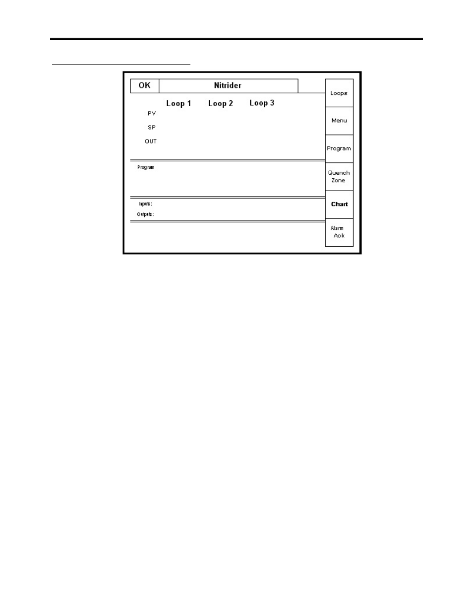
Default status screen
Display
The
Status
display shows the controller information. This information includes data for Loop 1,
Loop2 and Loop 3, as well as data for up to four (4) gas flowmeters. The Status display also shows
the current Program status, Input/Output Events status and alarm indication. There are six active
buttons on the left side of the status display screen: Loops, Menu, Program, Quench Zone,
Chart and Alarm Ack.
• The “Loops” button will switch the display to the parameters for the active control loops, up to
nine parameters. The buttons on the right side of the operator interface allows the operator to
look at the “detail” for the loop designated.
• The “Menu” button will switch to the operator menu. The “blue” UP and DOWN arrow keys
move you from one selection to another.
• The “Program” button will switch to the program display. This is a companion display to the
status screen and is described below.
• The “Quench Zone” button (generally NOT used with the Nitriding Process) will switch to the
Quench and Zone display. This is a companion display to the status screen and is described
below.
• The “Chart” button will switch the display to the video recorder display. Use of the “Chart”
display is explained below.
• The “Alarm Ack” button will switch to the Active Alarms screen. All Active alarms are displayed
on this screen. To acknowledge an alarm, press the UP or DOWN arrow keys to highlight the
alarm and press the “Ack” button, located in the lower left side of the screen, to acknowledge
the alarm. To acknowledge multiple alarms, repeat the process just described. Return to the
Status screen by pressing the “Esc” button.