Super Systems 9210 Series User Manual
Page 29
M4557 - Model 9210 Nitriding Controller
SSi Manual SERIES 9210-M4557-Nitriding
Page 29 of 29
•
Programmer alarm
•
Alarm 1
•
Alarm 2
•
Alarm 3
•
Event 0 through Event 15
•
Burn off
•
IN 1 Relay SP A
•
IN 1 Relay SP B
•
IN 1 Relay SP C
•
IN 2 Relay SP A
•
IN 2 Relay SP B
•
IN 2 Relay SP C
•
IN 3 Relay SP A
•
IN 3 Relay SP B
•
IN 3 Relay SP C
•
Alarm Combination (can be any combination below)
•
Programmer Alarm
•
Alarm 1
•
Alarm 2
•
Alarm 3
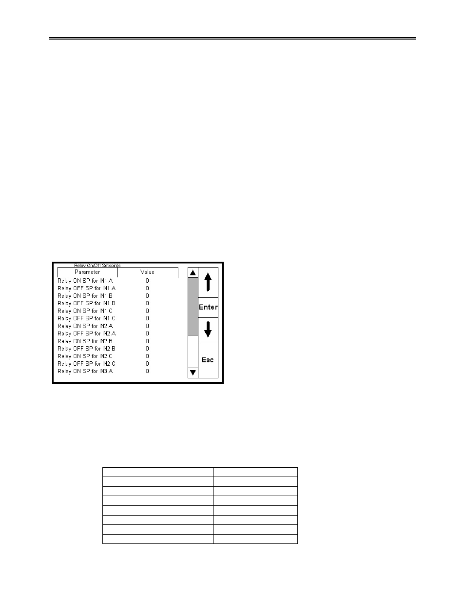
Relay Set Points
This menu screen is not used and should be ignored.
Contact Super Systems Inc at 800-666-4330 before
making any changes to this screen. This screen will
allow the user to set the ON/OFF setpoints for Input
1, 2, and 3 A, B, and C relays. Selecting a setpoint to
modify and pressing the Enter button will display a
numeric keypad. This can range from –9999 to
9999.
Analog Input Setup
This menu option displays a two-level screen with the top level showing the three inputs. Use the blue up
and down arrow keys to select one of the inputs.
Pressing the “Enter” key takes you to a menu of parameters that can be assigned to any of the three
inputs. Included are thermocouples, voltage, and current inputs.
The lower zone of the “Analog Input Setup” screen contains a table:
Parameter Value
TC Type
S
Filter Time
0
Initial Scale
0
Full Scale
3000
Decimal Point Location
0
Open TC
Up scale
Input offset
0