Super Systems 9210 Series User Manual
Page 30
M4557 - Model 9210 Nitriding Controller
SSi Manual SERIES 9210-M4557-Nitriding
Page 30 of 30
Use curve
0
Select the “TC Type” option and press the Enter button. This will display a screen with the different input
types available.
Note: See the Input type selections for the Series 9210 below for the different input types
available
. The “Filter Time” selection will display a numeric keypad from which the user can enter the new
filter time. This can range from 0 to 9999. The “Initial Scale” selection will display a numeric keypad from
which the user can enter the new initial scale. This can range from -9999 to 9999. The “Full Scale”
selection will display a numeric keypad from which the user can enter the new full scale. This can range
from –999- to 9999. The “Decimal Point Location” selection will display a numeric keypad from which the
user can enter the new decimal point location. This can range from 0 to 4. The “Open TC” selection will
display a screen from which the user can enter the new filter time. This can be either Up Scale or Down
Scale. The “Input Offset” selection will display a numeric keypad from which the user can enter the new
input offset. This can range from -10 to 10. The “Use Curve” selection will display a numeric keypad from
which the user can enter the new curve to use. This can range from 0 to 5. 0 means no curve is used.
Continue until all values associated/required by the input type have been entered. Pressing the Esc key
takes you back to the configuration menu.
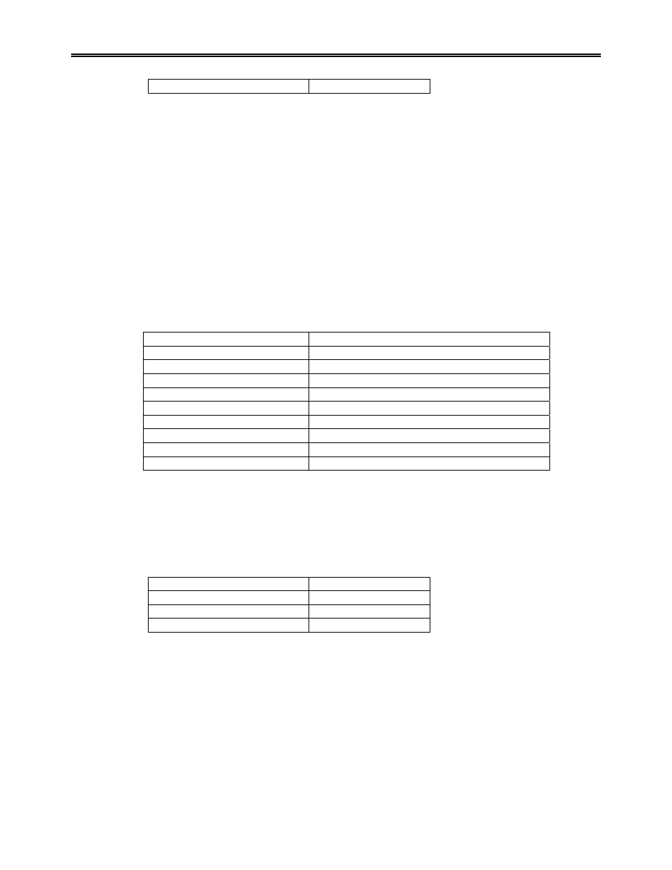
Input type selections for the Series 9210:
Input Type Options
T/C’s B, C, E, J, K, N, NNM, R, S, T
2.5
Volts
1.25
Volts
78.125
Millivolts
19.53125
Millivolts
4 – 20 mA (124 Ohm precision shunt required)
25 Volts (Requires internal jumper)
12.5 Volts (Requires internal jumper)
781.25 Millivolts (Requires internal jumper)
195.3125 Millivolts (Requires internal jumper)
Analog Output Setup
This menu screen is similar in function to the
Analog Input Setup
screen, with the exception that these are
analog outputs, not inputs. There are two analog output available. The top blue up and down arrow keys
highlight either Output 1 or Output 2. The lower blue up and down arrow keys will allow the user to set up
the analog output settings.
Parameter Value
Assignment
PV 2 retrans
Offset 0
Range 100
The “Assignment” selection will display a screen from which the user can select the new assignment. For
example you can re-transmit PV1 (Process Variable 1 - %C) to a chart recorder or an analog input board in
a PLC. In most Nitrider applications Output 1 is used to control the backpressure and Output 2 is used for
Temperature control. The list of options is:
PV 1 retrans
Loop 1 Inc
Loop 1 Dec
Loop 1 Combo
PV 2 retrans
Loop 2 Inc