Super Systems 9210 Series User Manual
Page 34
M4557 - Model 9210 Nitriding Controller
SSi Manual SERIES 9210-M4557-Nitriding
Page 34 of 34
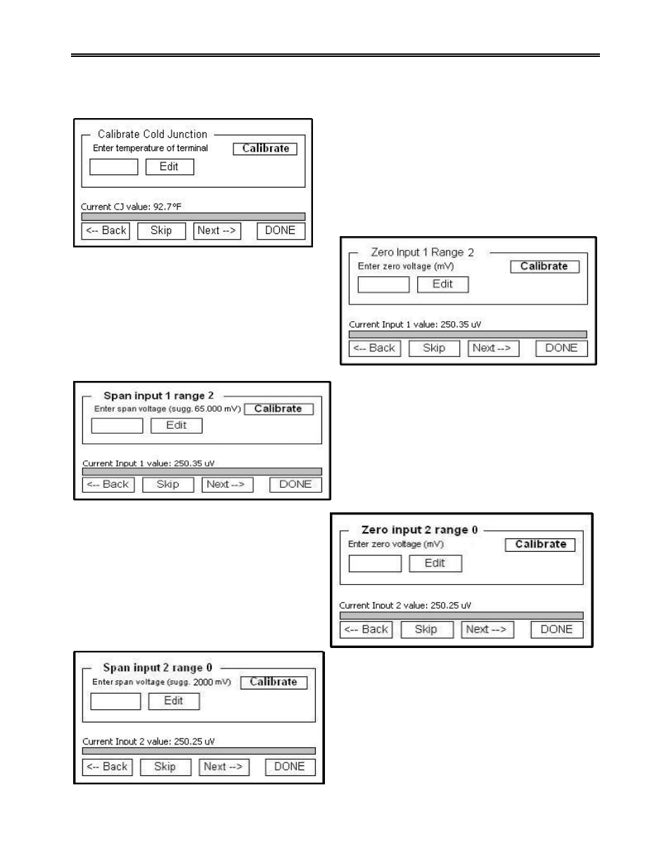
Calibration
menu. The Edit button will display a numeric keypad from which the user can enter a new
value for the calibration process. The Calibrate button will begin the calibration process for the selected
screen
.
The first screen in the
User Calibration
menu is the
Calibrate Cold Junction screen. This will allow the user
to enter an offset for the cold junction value. The
current value is displayed directly above the progress
bar and bottom row of buttons as “Current CJ value:
XX.X ° F”. Press the Calibrate button to set the cold
junction offset. The progress bar at the bottom of the
screen will display the calibration progress.
The next screen is the Zero Input 1 Range 2 screen.
This screen will allow the user to set the zero scale
for Input 1 Range 2. A value of 0 millivolts will need
to be sourced to the inputs. For a zero calibration,
enter a 0 as the value of the terminal to correctly
calibrate the inputs. The current Input 1 value will
be displayed near the bottom of the screen as
“Current Input 1 value: xxxx.xx uV”. The progress
bar at the bottom of the screen will display the calibration progress.
The next screen is the Span Input 1 Range 2 screen.
This screen will allow the user to set the span value
for Input 1 Range 2. A suggested value will be
displayed next to the Calibrate button (“sugg.
65.000 mV”). The current Input 1 value will be
displayed near the bottom of the screen as “Current
Input 1 value: xxxx.xx uV”. The progress bar at the
bottom of the screen will display the calibration
progress.
The next screen is the Zero Input 2 Range 0
screen. This screen will allow the user to set the
zero scale for Input 2 Range 0. A value of 0
millivolts will need to be sourced to the inputs.
For a zero calibration, enter a 0 as the value of
the terminal to correctly calibrate the inputs. The
current Input 2 value will be displayed near the
bottom of the screen as “Current Input 2 value:
xxxx.xx uV”. The progress bar at the bottom of
the screen will display the calibration progress.
The next screen is the Span Input 2 Range 0 screen.
This screen will allow the user to set the span value
for Input 2 Range 0. A suggested value will be
displayed next to the Calibrate button (“sugg. 2000
mV”). The current Input 2 value will be displayed
near the bottom of the screen as “Current Input 2
value: xxxx.xx uV”. The progress bar at the bottom
of the screen will display the calibration progress.