Super Systems 9210 Series User Manual
Page 28
M4557 - Model 9210 Nitriding Controller
SSi Manual SERIES 9210-M4557-Nitriding
Page 28 of 28
Alarm Setup
The Alarm Setup menu is a two-level screen. The first level allows you to select the alarm – Alarm1 –
Alarm 3. The Second level scrolls through the alarm parameters.
Parameter Value
Setpoint 2500
Alarm Type
PV2 proc high
Hysteresis 1
Using the lower blue up and down arrow keys, select the parameter to modify, and then press the Enter
button. The “Setpoint” selection will allow the user to enter the setpoint for the alarm. This will display a
numeric keypad. This can range from –9999 to 9999. The “Alarm Type” selection will allow the user to
set the type of alarm. This will display a two-level screen. The top level has the following options:
Process High
Process Low
Band, Normally Open
Band, Normally Closed
Deviation, Normally Open
Deviation, Normally Closed
The bottom level has the following options:
PV 1 Value
PV 2 Value
PV 3 Value
Input 1 Value
Input 2 Value
Input 3 Value
PO1 Value
PO2 Value
PO3 Value
The “Hysteresis” selection will allow the user to set the hysteresis. This will display a numeric keypad. This
can range from 0 to 9999.
If you are configuring more than one alarm, follow the above instructions for each alarm that you are
configuring.
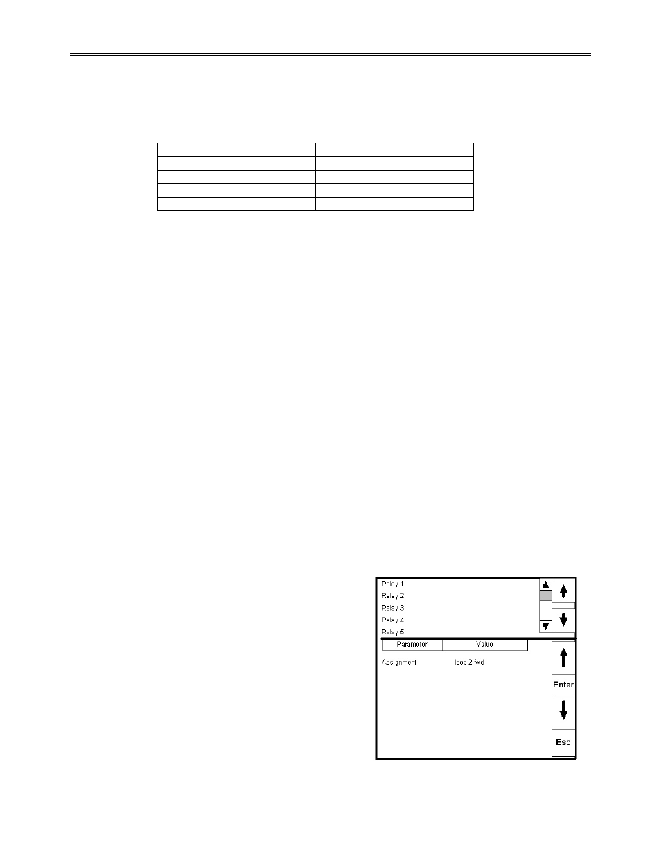
Relay Assignment
This menu selection allows the user to assign the action to
the selected Relay Output.
All eight of the 9210’s relay outputs are assigned in this
screen. To select a Relay Output to modify, use the up or
down arrow keys to highlight the event.
Highlighting the “Assignment” selection that you wish to
assign and pressing the Enter button takes you to a screen
that has the following choices
•
Loop 1 fwd
•
Loop 1 rev
•
Loop 2 fwd
•
Loop 2 rev
•
Loop 3 fwd
•
Loop 3 rev