Connecting the pse9000-d dc power cords – H3C Technologies H3C S12500 Series Switches User Manual
Page 46
36
Six pairs of wiring terminals (marked PSR1 through PSR6) are available on the DC terminal block of the
S12504 switches. Eight pairs of wiring terminals (marked PSU1 through PSU8) are available on the DC
terminal block of the S12508/S12518. The wiring terminals correspond to the power modules. The
power source provides power to the switch through the wiring terminals. If slot 1 is installed with a power
module, the wiring terminals marked PSR1 or PSU1 must be connected to the power source with a DC
power cord to make the power module operate correctly.
Connecting the PSE9000-D DC power cords
The S12504-DC model adopts the PSE9000-D DC power system.
To connect the PSE9000-D DC power cords:
1.
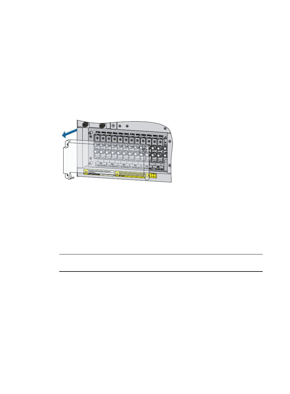
Remove the protection cover from the terminal block.
Figure 36 Removing the protection cover from the terminal block
2.
Loosen the fastening screw on the marked with RTN(+) with an M6 wrench, and remove the screw,
spring washer, and flat washer.
3.
Connect the ring terminal of the black DC power cord to the wiring terminal marked with RTN(+),
install the flat washer, spring washer, and fasten the screw.
4.
Connect the ring terminal of the blue DC power cord to the negative terminal (–) on the terminal
block.
5.
Connect the ring terminal of the grounding cable to the wiring terminal marked with PE on the
rightmost of the terminal block.
NOTE:
Grounding cables for power frames are user-supplied.