H3C Technologies H3C S12500 Series Switches User Manual
Page 51
41
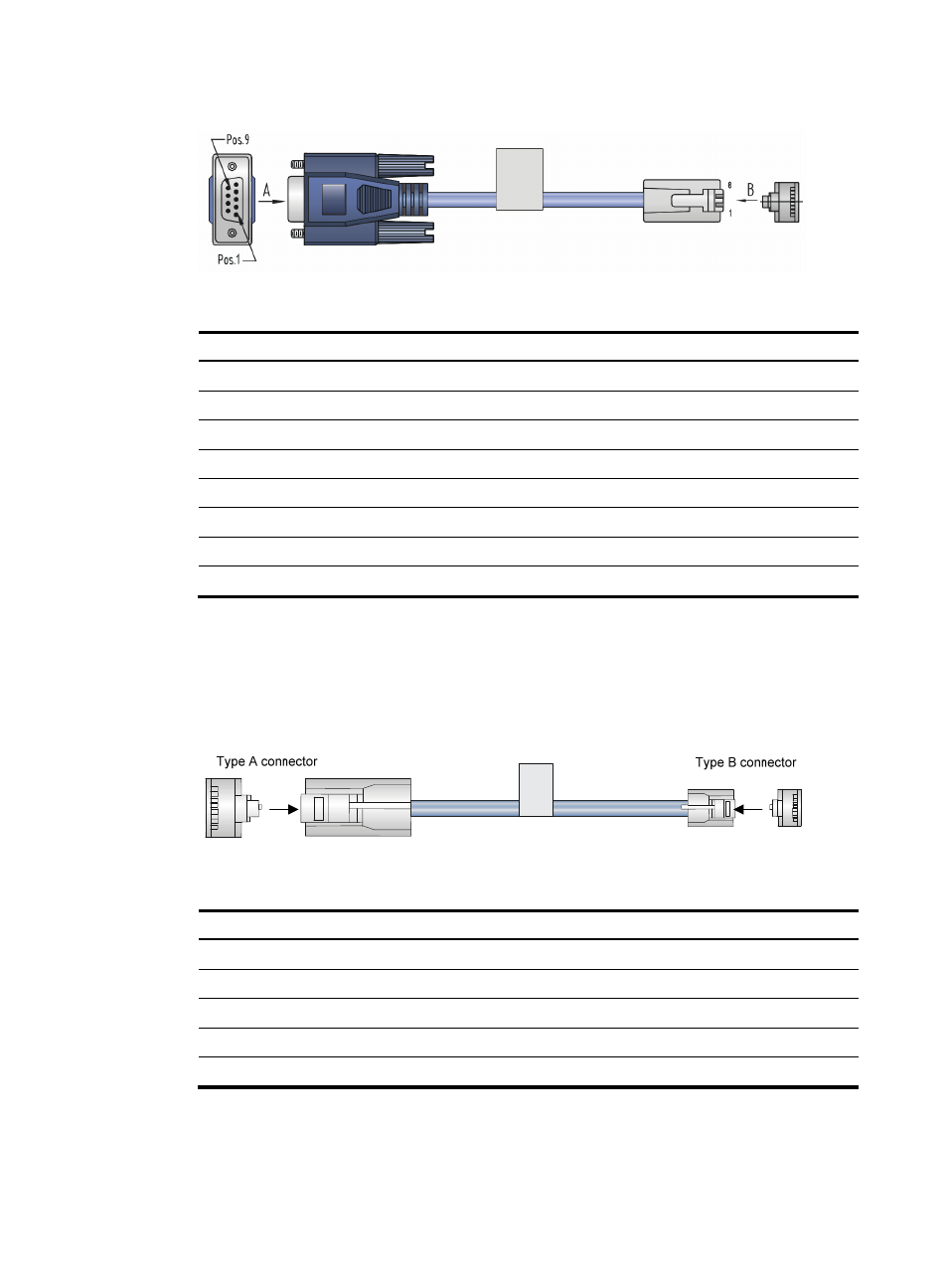
Figure 41 Console cable connecting the serial port and the console port
Table 9 Pinouts for the console cable connecting the serial port and the console port
RJ-45 pin Signal
DB-9 pin
Signal
1 RTS
8 CTS
2 DTR
6 DSR
3 TXD
2 RXD
4 CD
5 SG
5 GND
5 SG
6 RXD
3 TXD
7 DSR
4 DTR
8 CTS
7 RTS
•
Console cables connecting the USB console port on a switch and the USB port on a PC or terminal
The console cable consists of one mini-USB A/B connector for connecting to the USB console port
on the switch and one USB A connector for connecting to the USB port on the PC or terminal.
shows the console cable and
shows its pinouts.
Figure 42 Console cable connecting the USB port and the USB console port
Table 10 Pinouts for the console cable connecting the USB port and the USB console port
USB A pin
Signal
mini-USB A/B pin
Signal
1 VBUS
1
VBUS
2 D-
2
D-
3 D+
3
D+
4
ID(NC)
4 GND
5
GND