Viewing voice device topologies – H3C Technologies H3C Intelligent Management Center User Manual
Page 79
70
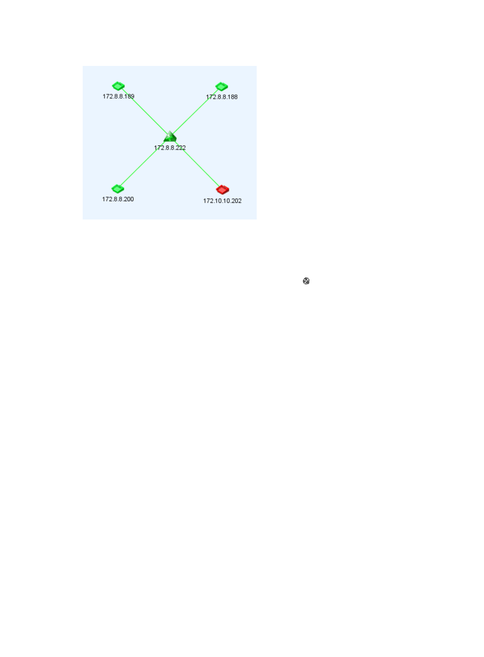
Figure 7 Voice region topology
To view a voice region topology:
1.
Click the Service tab.
2.
From the left navigation tree, select Voice Service Manager > Resource View > VCX Devices.
3.
On the VCX Device List, click the Display device topology icon in the Operation column for the
target VCX device.
The VCX device topology window appears.
4.
From the left navigation tree, double-click the target node under Topology > Voice View > Voice
Region.
5.
On the topology, click the icon of the target VCX device.
The following information appears:
{
Label—Device label of the VCX device in VSM.
{
IP Address—IP address of the VCX device.
{
Site ID—Site ID of the VCX device.
{
Primary Call Processor—IP address of the primary call processor of the VCX device.
{
Secondary Call Processor—IP address of the secondary call processor of the VCX device.
{
Primary IP Messaging—IP address of the primary IP messaging server of the VCX device.
{
Secondary IP Messaging—IP address of the secondary IP messaging server of the VCX device.
{
Primary Data Server—IP address of primary data server of the VCX device.
{
Secondary Data Server—IP address of secondary data server of the VCX device.
{
Whether the Device is a Billing Server—Whether or not the VCX device is a billing server.
{
Number of IP Phones—Number of IP phones that are registered on the VCX server.
6.
Double-click the VCX device icon to view the VCX device and the registered IP phones on a VCX
device topology. For more information, see “
Viewing voice device topologies
”.
Viewing voice device topologies
A voice device topology displays all managed VCX and NBX devices in VSM and the logical
connections to the connected IP phones.