Page, 9gt490x engineer’s reference guide – RISCO Group Gardtec 490X User Manual
Page 10
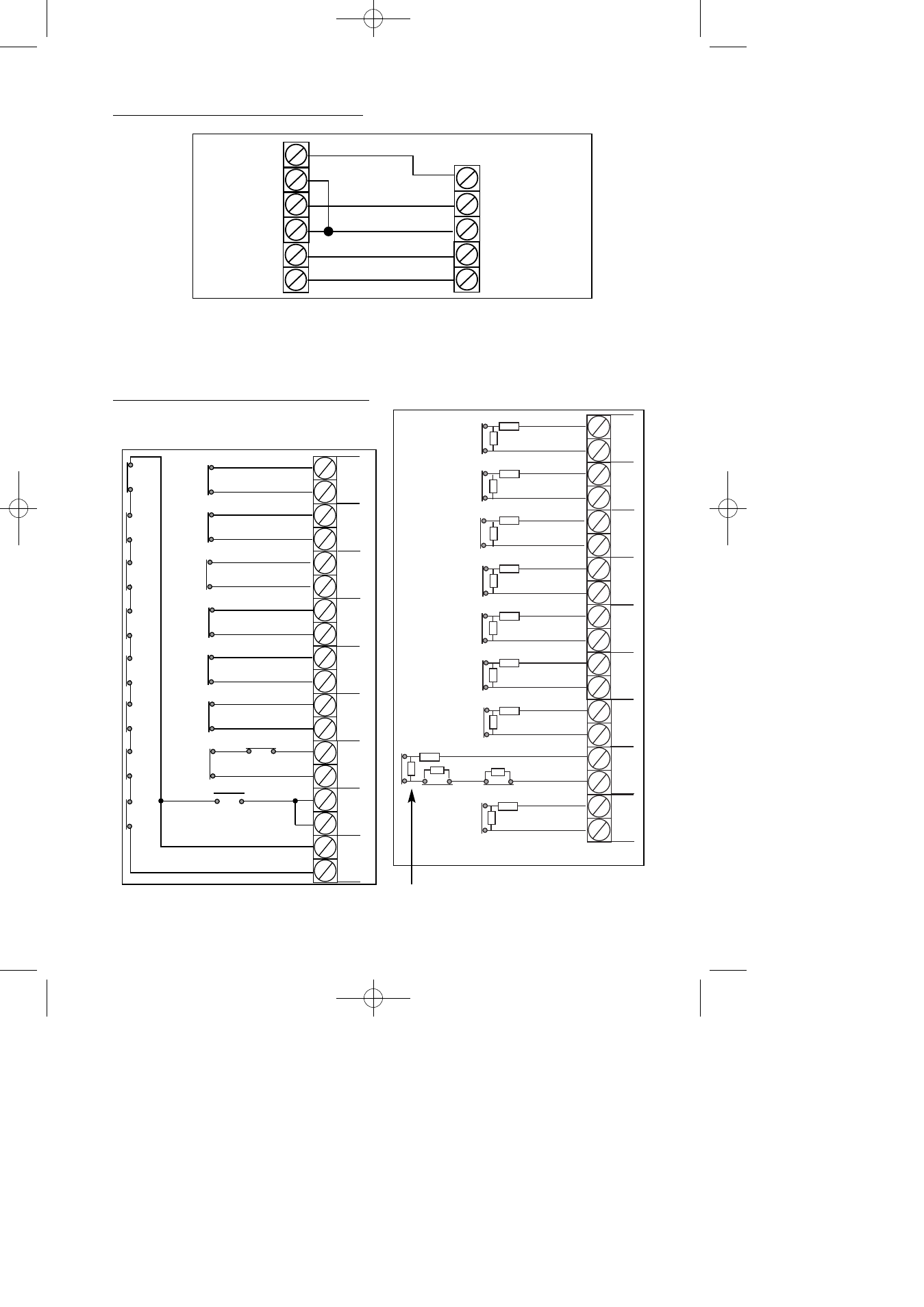
Typical Novagard 2G/2G Connections
Control Panel Input (Zone Connection)
Page
9
GT490X Engineer’s Reference Guide
+12V
0V
S-
ST-
R TMP
F TMP
BELL+
BELL-
SAB TMP
BELLHOLD-
STROBE-
NovaGard 2G/4G
(Strobe terminals omitted)
GT490X Control Panel
AZ1
+ -
AZ2
+ -
AZ3
+ -
AZ4
+ -
AZ5
+ -
AZ6
+ -
AZ7
+ -
AZ8
+ -
N/C Devices
N/C Devices
N/C Devices
N/C Devices
N/C Devices
N/C Devices
6k8
6k8
6k8
6k8
6k8
6k8
6k8
6k8
N/C Devices
N/C Devices
6k8
6k8
4k7
4k7
4k7
4k7
4k7
4k7
4k7
4k7
TZ
+ -
6k8
Tamper Zone
becomes Zone 9
ONLY when 9 (EOL)
is selected
4k7
N/C Devices
End of Line Zone Wiring
Multiple units can only be used with BS Standard.
If using EN2, one unit per zone.
AZ1
+ -
AZ2
+ -
AZ3
+ -
AZ4
+ -
AZ5
+ -
AZ6
+ -
AZ7
+ -
AZ8
+ -
TZ
+ -
N/O Devices (PA etc)
connect across Tamper & Zone
N/C Devices
multiple devices are in series
N/C Devices
N/C Devices
N/C Devices
N/C Devices
N/C Devices
N/C Devices
Standard (2 Wire) Zone Wiring
Please see following page for further wiring modes
where Anti-Mask detectors are used
PR5851 Rev12 490X Eng Ref Guide.qxd 10/05/2012 11:32 Page 9