Altera Arria V SoC Development Board User Manual
Page 11
Chapter 2: Board Components
2–3
Board Overview
July 2014
Altera Corporation
Reference Manual
SW2
Board settings DIP switch
Controls the MAX V CPLD 5M2210 System Controller functions such
as clock enable, SMA clock input control, and which image to load
from flash memory at power-up.
SW3
MSEL DIP switch
Controls the configuration scheme on the board. MSEL pins 0, 1, 2, 3,
and 4 connects to the DIP switch.
S13
Program select push button
Toggles the program select LEDs, which selects the program image
that loads from flash memory to the FPGA.
S12
Configure push button
Load image from flash memory to the FPGA based on the settings of
the program select LEDs.
D38
Configuration done LED
Illuminates when the FPGA is configured.
D40
Load LED
Illuminates when the MAX V CPLD 5M2210 System Controller is
actively configuring the FPGA.
D39
Error LED
Illuminates when the FPGA configuration from flash memory fails.
D37
Power LED
Illuminates when 5.0-V power is present.
D35, D36
JTAG TX/RX LEDs
Indicate the transmit or receive activity of the JTAG chain. The TX and
RX LEDs would flicker if the link is in use and active. The LEDs are
either off when not in use or on when in use but idle.
D41–D43
Program select LEDs
Illuminates to show which flash memory image loads to the FPGA
when you press the program select push button. Refer to
the LED settings.
D8, D20
FMC port present LEDs
Illuminates when a daughter card is plugged into the FMC port.
D21–D24
UART LEDs
Illuminates when UART transmitter and receiver are in use.
Clock Circuitry
X2
Programmable oscillator
Si570 programmable oscillator with a default frequency of 100 MHz.
The frequency is programmable using the clock control GUI running
on the MAX V CPLD 5M2210 System Controller.
X3
148.5-MHz oscillator
Si571 programmable oscillator with a default frequency of 148.5 MHz.
The frequency is programmable using the clock control GUI running
on the MAX V CPLD 5M2210 System Controller.
X4
50-MHz oscillator
50.000-MHz crystal oscillator for general purpose logic.
X5
125-MHz oscillator
125.000-MHz crystal oscillator for general purpose logic.
J15
Clock input SMA connector
Drive LVCMOS-compatible clock input into the dedicated clock pin.
J49
HPS SMA clock
Drive LVCMOS to HPS clock multiplexer.
U35
Multi-output oscillator
Si5338A quad-output fixed oscillator with 25M, 25M, 100M, and 100M
outputs.
General User Input/Output
D9–D16
User LEDs
Four user LEDs and four HPS LEDs. Illuminates when driven low.
SW1
User DIP switch
User DIP switch. When the switch is ON, a logic 0 is selected.
S14
CPU reset push button
Reset the FPGA logic.
S11
MAX V reset push button
Reset the MAX V CPLD 5M2210 System Controller.
S1–S8
General user push buttons
Four user push buttons and four HPS push buttons. Driven low when
pressed.
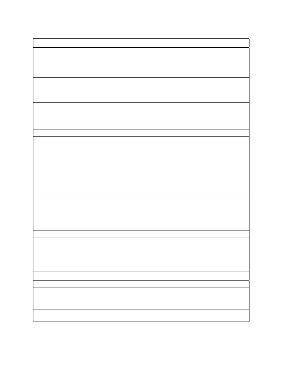
Table 2–1. Board Components (Part 2 of 3)
Board Reference
Type
Description