Connection diagrams – CIRCUTOR DISPENSER Series User Manual
Page 79
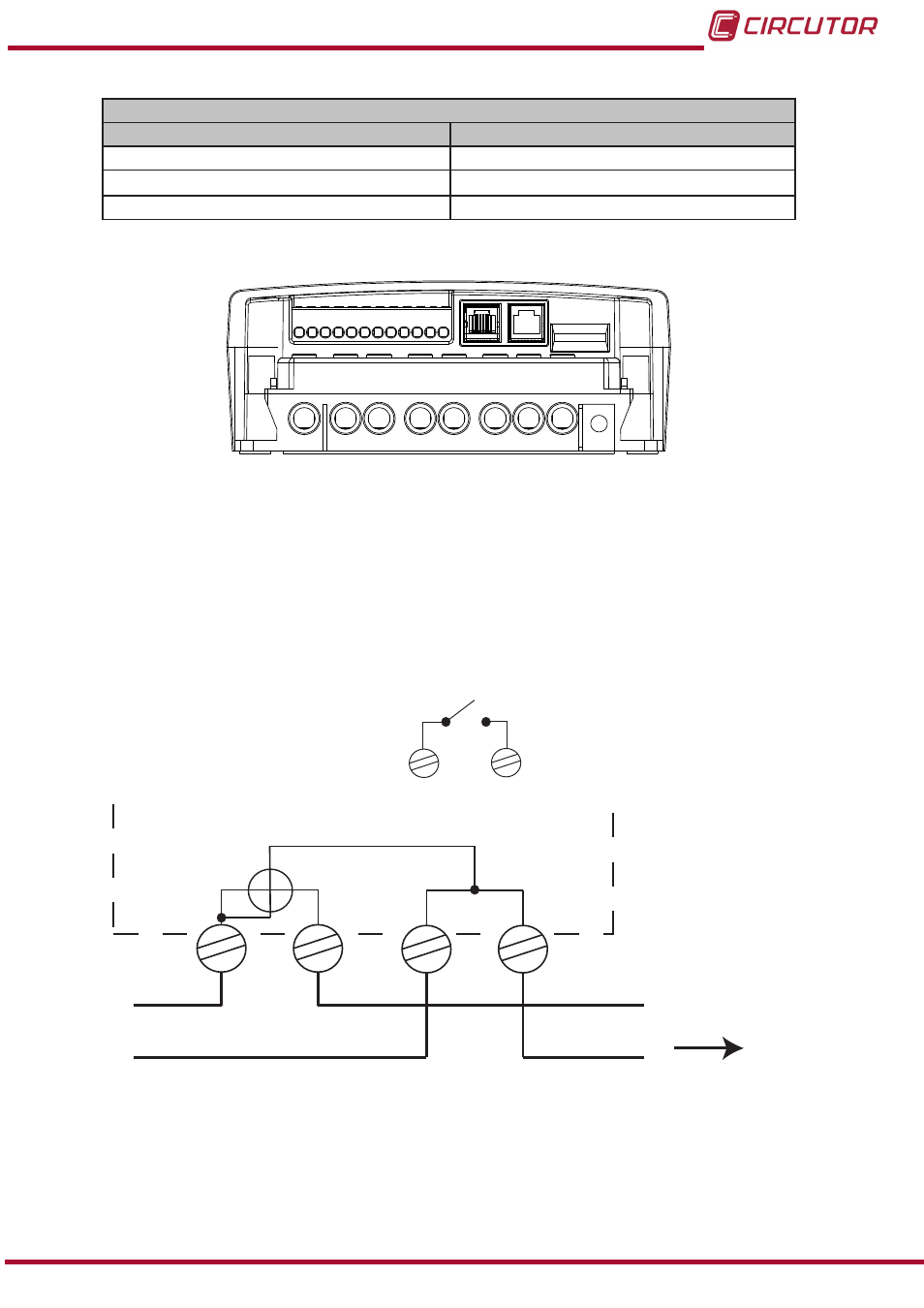
Table 30:List of terminals of the three-phase Dispenser Universal (RS-485 Communications)�
Unit terminals
RJ Connector
DB9 Connector
(12)
1, 6: GND, RS-485 communications
5: GND, RS-485 communications
4: A(+), RS-485 communications port
6: TD(-), RS-485 communications port
5: B(-), RS-485 communications port
7: TD(+), RS-485 communications port
(12)
The DB9 connector is found on the lower front cover of the unit and it is connected to the RJ connector.
Figure 87: Terminals of the three-phase Dispenser Universal (RJ Communications connector)�
5�1�4�- CONNECTION DIAGRAMS
5�1�4�1�- SINGLE-PHASE MODEL�
shows that terminals
1 and 3 must be inserted into the phase line and terminals 4 and
6 into the neutral line.
3
4
6
L
N
CARGA / LOAD
23
24
1
Figure 88: Connection diagram of the single-phase Dispenser Universal�
Note: The diagram also shows the terminals of the auxiliary relay, 23 and 24.
79
Instruction Manual
Dispenser Universal System